- 2 -
1.1.4. Additional Functions
These instruments contain a number of functions in addition to reporting flow which include:
• Settable alarms and warnings with semiconductor switch outputs
• A digitally reported status of alarms and warnings such as overflow/underflow
• A flow totalizer to track the amount of gas added to a system
• A digitizing channel for an auxiliary analog signal
• An internal curve fitting routine for “fine tuning” the base calibration
• An alternate calibration set of 8 different ranges/gases
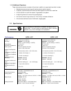
1.2. Specifications
Performance
HFM-I-401 HFM-I-405
Full Scale Flow Ranges
(in N
2
)
0-10 slm up to 0-350 slm 0-100 slm up to 0-2500 slm
Accuracy
1
Standard: ± 1% full scale Standard: ± 1% full scale
Optional: ± (0.5% reading + 0.2%FS) Optional: ± (0.5% reading + 0.2%FS)
Repeatability ± 0.1% of F.S. ± 0.1% of F.S.
Operating Temperature -20 to 70°C -20 to 70°C
Warm up time 30 min for optimum accuracy 30 min for optimum accuracy
2 min for ± 2% of full scale 2 min for ± 2% of full scale
Settling Time/Reponse
Time
< 2.5 seconds (to within ± 2% of full scale) < 2.5 seconds (to within ± 2% of full scale)
Temperature Coefficient
of Zero
< ±0.05% of Full Scale /°C < ±0.05% of Full Scale /°C
Temperature Coefficient
of Span
< ±0.16% of reading/°C < ±0.16% of reading/°C
Operating Pressure -
Maximium
Standard: 500 psig Standard: 500 psig
Optional: 1500 psig Optional: 1000 psig
Pressure Coefficient of
Span < 0.01%of reading /psi (N
2
, 0-1000 psig) < 0.01%of reading /psi (N
2
, 0-1000 psig)
Pressure Drop(N
2
@14.7
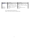
psia) < 1.1 psi at full scale flow < 5.1 psi at full scale flow
Attitude Sensitivity of
Zero < 2% of F.S. < 2% of F.S.
Electrical
Power Requirements
18-38 VDC, 3.5 watts(Ethernet) 2.5
watts(RS232/485)
18-38 VDC, 3.5 watts(Ethernet) 2.5
watts(RS232/485)
Analog Output
Standard: 4 – 20 mA Standard: 4 – 20 mA
Optional: 0-10 VDC, 0-20 mA, 0-5 VDC, 1-5 VDC Optional: 0-10 VDC, 0-20 mA, 0-5 VDC, 1-5 VDC
Digital Output
Standard: RS 232 Standard: RS 232
Optional: RS 485 Optional: RS 485
Optional: Ethernet Optional: Ethernet
Analog Connector
Std: Terminal Block – PG 9 Cable Gland Std: Terminal Block – PG 9 Cable Gland
Optional: 12 pin Circular Connector Optional: 12 pin Circular Connector
WARNING
Do not operate this instrument in excess of the specifications
listed below. Failure to heed this warning can result in serious
personal injury and/or damage to the equipment.


