- 4 -
Installation
2. Installation
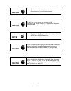
CAUTION
Many of the functions described in this section require
removing the enclosure front plate. Care must be taken when
reinstalling this plate to ensure that the sealing gasket is
properly positioned and the fasteners are secure to maintain
an IP65 compliant seal.
2.1. Receiving Inspection
Your instrument has been manufactured, calibrated, and carefully packed so it is ready for
operation. However, please inspect all items for any obvious signs of damage due to shipment.
Immediately advise Teledyne Hastings and the carrier if any damage is suspected.
Use the packing slip as a check list to ensure all parts are present (e.g. flow meter, power
supply, cables etc.) and that the options are correctly configured (output, range, gas,
connector).
If a return is necessary, obtain an RMA (Return Material Authorization) number from Teledyne
Hastings’ Customer Service Department at 1-800-950-2468 or
hastings_instruments@teledyne.com
.
2.2. Environmental and Gas Requirements
Use the following guidelines prior to installing the flow meter:
• Ensure that the temperature of all components and gas supply are
between -20° and 70° C
• Ensure that the gas line is free of debris and contamination
• Ensure that the gas is dry and filtered (water and debris may clog the
meter and/or affect its performance)
• If corrosive gases are used, purge ambient (moist) air from the gas lines
2.3. Mechanical Connections
The meter can be mounted in any orientation unless using dense gases or pressures higher than
250 psig in which case a “flow horizontal” orientation is required. The meter’s measured flow
direction is indicated by the arrow on the electronics enclosure.
A straight run of tubing upstream or downstream is not necessary for proper operation of the
meter. The flow meter incorporates elements that pre-condition the flow profile before the
measurement region. So for example, an elbow may be installed upstream from the flow meter
entrance port without affecting the flow performance.
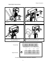
Compression fittings should be connected and secured according to recommended procedures
for that fitting. Two wrenches should be used when tightening fittings (as shown in the Quick
Start Guide on page iii) to avoid subjecting the flow meter body to undue torque and related
stress.
The fittings are not intended to support the weight of the meter. For mechanical structural
support, four mounting holes (#1/4-20 thread, 3/8” depth) are located in the bottom of the
meter. The position of these holes is documented on the outline drawing in Appendix 3 (Section
6.3).
Leak-check all fittings according to an established procedure appropriate for the facility.


