


- 17 -
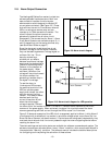
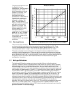
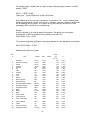
The gas properties which form
the basis for the flow
measurement, such as viscosity
and specific heat, exhibit a
slight dependence on the gas
pressure. Fortunately, this
pressure dependence is
predictable and can be
corrected for in cases where it
has an impact on accuracy
(typically only significant for
pressures in excess of 100
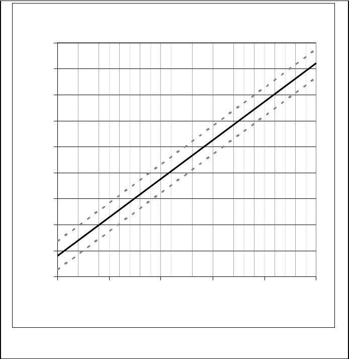
psig). The graph shown in
Figure 3-1 shows the expected
span shift as a function of
pressure for nitrogen. This
behavior is similar for most
diatomic gases (O
2
, H
2,
etc),
whereas this effect is
insignificant for the monatomic
gases (He, Ar, etc). This span
shift must be considered and
accounted for as appropriate
for accurate flow
measurements at high pressure
conditions.
3.6. Warnings/Alarms
There are two alarm contacts
on the terminal strip connector within the electronics enclosure (See Section 2.8). These
function as isolated semiconductor switches sharing a single, isolated common line. In its
normal state each switch is “open”; when an alarm is activated the switch is “closed”.
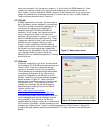
The meter’s processor can be configured via the digital interface to establish the internal
condition for activating each alarm. There are many choices for internal alarms and warnings
including overflow, underflow, or various instrument error conditions. Each alarm can also be
given a selectable “wait time”—a period for which it must remain in the alarm condition before
the physical alarm is activated. See the Software Manual for detailed alarm setting and
configuration information.
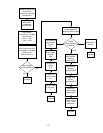
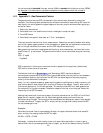
3.7. Multi-gas Calibrations
The Hastings 400 Series flow meters can have up to eight different calibrations stored
internally. These are referred to as gas records. These records are typically used to represent
different gases, but they can also be useful in other ways; for instance reporting the flow in an
alternate range, flow unit or reference temperature. The records are referred to by their
number label from #0 – #7. The first six records are, by default, setup for the same range in the
most common six gases as shown in Figure 2-11. If a gas other than one of these six is specified
on the customer order it will be placed in record #6. If a second different gas is selected, it
will be placed in record #7. If multiple different gases or ranges are specified they will replace
some of the standard six gases. Only the gas(es) specified on the order will be verified. The
other records will use nominal gas factors to approximate the gas sensitivity until an actual
calibration is performed to correct for individual instrument variations. Selecting the active gas
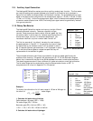
record can be done in one of two ways—a hardware setting or a software setting. The hardware
setting is done by accessing a rotary encoder on the upper PC board in the electronics
enclosure. When set to a number position from 0 to 7 it activates the corresponding gas record.
When set to a number greater than 7, the gas record control is passed to software. If the
software setting mode is enabled, then the “S6” digital command can be used to set the active
gas record as shown in the example below.
Figure 3-1 The pressure effect on flow calibration (for nitrogen)
Pressure Effect
-1
0
1
2
3
4
5
6
7
8
0 200 400 600 800 1000
Line Pressure (psig)
Span Shift (% Reading)