


- 14 -
Operation
3. Operation
The Hastings 400 Series flow meters are designed for operation with clean dry gas and in specified
environmental conditions (See Section 1.2). The properly installed meter measures and reports the
mass flow as an analog signal and, depending on the configuration and set up, as a digital response.
Other features can assist in the measurement operation and provide additional functions. The following
sections serves as a guide for correctly interpreting the analog and digital flow output, optimizing the
performance, and using the additional features of the instrument.
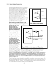
3.1. Environmental and Gas Conditions
For proper operation, the ambient and gas temperatures must be such that the flow meter
remains between -10 and 70°C. Optimal performance is achieved when the environment and
gas temperatures are equilibrated and stable. The 400 I series is intended for use with clean,
non-condensing gases only. Particles, contamination, condensate, or any other liquids which
enter the flow meter body may obstruct critical flow paths in the sensor or shunt, thus causing
erroneous readings.
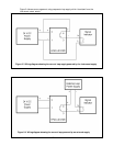
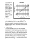
3.2. Interpreting the Analog Output
The analog output signal is proportional to mass flow rate. Each instrument is configured to
provide one of the available forms of analog output as described in Section 2.2. The signal read
by an indicator (for example, a process ammeter, data acquisition system, or PLC board) can
be mapped to the measured flow rate by applying the proper conversion equation selected
from the table below.
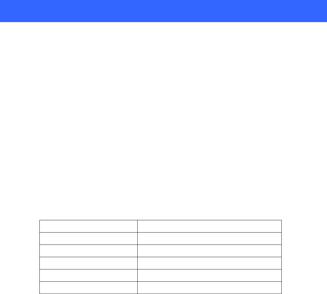
Table 3-1 The Signal → Flow mapping equations
Analog Output Configuration Mapping Equation
4 -20 mA Flow = FS flow * (I
out
– 4)/ 16
0 -20 mA Flow = FS flow * I
out
/ 20
0 – 5 Vdc Flow = FS flow * V
out
/ 5
0 – 10 Vdc Flow = FS flow * V
out
/ 10
1 – 5 Vdc Flow = FS flow * (V
out
-1)/ 4
Alternatively an analog display meter can indicate the flow rate directly in the desired flow
units by setting the offset and scaling factors properly.
The flow meter is typically able to measure and report flow which slightly exceeds the full
scale value. Reverse or “negative” flows are indicated (to values up to 25% of full scale) by
meters with 4-20 mA or 1-5 volt output. However, meters with 0-5 Volt, 0-10 volt or 0-20 mA
output are limited in their ability to indicate a negative flow with the analog signal since
negative currents or voltages cannot be generated by the meter’s circuitry.
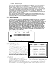
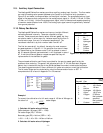
3.3. Digital Communications
Many of the Hastings 400 Series flow meter’s operating parameters such as the flow
measurement, alarm settings, status, or gas type can be read or changed by digital
communications. The digital communications commands and protocols for each particular
interface (RS-232, RS-485, and Ethernet) are treated in detail in the Software Manual.
However, the function and interpretation of flow output and auxiliary input are also briefly
presented here.