- 18 -
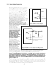
Example: To first determine and then change the active gas record using RS-232,
Computer transmits: {S6}
HFM flow meter replies: {0}
This indicates that gas record #0 is currently active.
Computer transmits: {S6=4}
This changes the active gas record to #4.
See the Software Manual for further information including how to setup a new gas record and
how to reconfigure an existing gas record.
3.8. Flow Totalization
The Hastings 400 Series flow meters are capable of providing a value for the “total amount of
gas” that has passed through the flow meter since the last time the totalization function was
reset. This value can be used to determine for example, the amount of gas used to fill a
chamber or drawn from a supply vessel. To initialize the totalization function, reset the
totalized flow value to zero using the S36 digital command as shown in the example below. All
subsequent flow readings are added over time and stored as the totalized flow value. The
totalized flow value can be read by querying the flow meter digitally as in the example below.
The totalized flow is reported in the flow units chosen for the active gas without the time unit.
For example, if the flow units are standard liters per minute, the totalized flow is reported in
standard liters; if flow units are standard cubic feet per hour, the totalized flow is reported in
standard cubic feet.
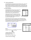
Example: For a 100 slm FS flow meter, to first reset/start the flow totalization function and
then later read the value using RS-232,
Computer transmits: {S36=0}
This resets the totalized value to zero and starts the totalization function. At some point later
in time:
Computer transmits: {S36}
HFM flow meter replies: {45.7}
This is interpreted as a total gas amount of 45.7 standard liters has passed through the meter
since the flow totalizer was started.
3.9. Additional Digital Capabilities
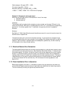
The Hastings 400 series flow meters have a wide selection of other functions, operating
parameters, and values that can be reported and configured via digital communications such as
the calibration date, the instrument temperature, the number of hours that gas has been
flowing, etc. See the Software Manual for detailed information on these additional digital
features.
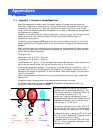
CAUTION
Accessing the rotary encoder requires removing the enclosure
front plate. Care must be taken when reinstalling this plate to
ensure that the sealing gasket is properly positioned and the
fasteners are secure to maintain an IP65 compliant seal.
NOTE
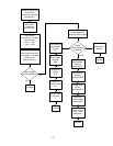
The software command to change the active gas record will not
be executed unless the rotary encoder is set to a number
greater than 7. However, the software query will return the
current active gas record number even when it has been set by
the hardware.


