


- 10 -
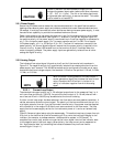
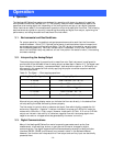
2.8. Alarm Output Connection
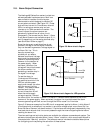
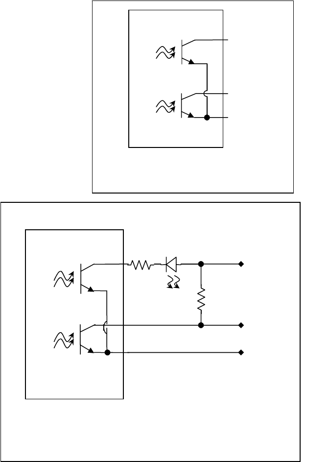
The Hastings 400 Series flow meters include two
software settable hardware alarms. Each is an
open-collector transistor functioning as a
semiconductor switch designed to conduct DC
current when activated. (See Figure 2-9.) These
sink sufficient current to illuminate an external
LED or to activate a remote relay and can
tolerate up to 70Vdc across the transistor. The
alarm lines and the alarm common are
galvanically isolated from all other circuit
components. The connections for Alarm 1, Alarm
2 and Alarm Common are available as pins 10, 11,
and 12 respectively on the analog terminal strip
(see Quick Start Guide on page iii).
Since the alarms act as switches they do not
produce a voltage or current signal. However,
they can be used to generate a voltage signal on
an Alarm Out line. This is
done by connecting a
suitable pull-up resistor
between an external voltage
supply and the desired alarm
line while connecting Alarm
Common to the common of
the power supply. When
activated, the alarm line
voltage will be pulled toward
the alarm common line
generating a sudden drop in
the signal line voltage.
To use the alarm to
illuminate an LED connect
the positive terminal of the
LED to a suitable power
supply and connect the other
end to a current limiting
resistor. This resistor should
be sized such that the
current is less than 20 mA
when the entire supply
voltage is applied. Connect
the other end of the resistor to Alarm 1 or Alarm 2. Connect Alarm Common to the circuit
common of the power supply. When activated, the alarm line is pulled toward the alarm
common generating sufficient current through the LED to cause it to illuminate.
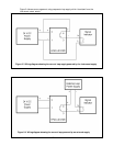
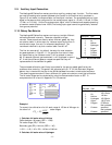
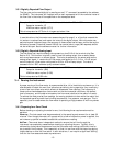
Figure 2-10 shows an example of the LED circuit arrangement applied to Alarm 1 while Alarm 2
is configured with a suitable pull-up resistor to provide a voltage output on an Alarm Out line.
Since the Alarm Common is a shared contact, if both alarms are being used independently they
must each be wired such that the current passes through the external signaling device before
reaching the alarm line.
The alarm settings and activation status are available via software commands and queries. The
software interprets an activated Alarm 1 as an “Alarm” condition, while an activated Alarm2 is
interpreted as a “Warning” condition. The software manual includes the detailed descriptions
for configuring and interpreting the activation of these alarms.
Alarm
1
Alarm 2
Alarm
Common
V +
Alarm Out
V -
Figure 2-10 Alarm circuit diagram for LED operation
Alarm 1
Alarm 2
Alarm Common
Figure 2-9 Alarm circuit diagram