


- 5 -
2.4. Mounting the Electronics Remotely
CAUTION
In order to maintain the integrity of the Electrostatic Discharge
immunity both parts of the remote mounted version of the
HFM-I-400 instrument must be screwed to a well grounded
structure. The ferrite that is shipped with the instrument must
be installed on the cable next to the electronics enclosure.
The electronics enclosure can be separated and
relocated up to 30 feet away from the flow
meter base. This requires a cable which is
supplied with the instrument if ordered as a
cable mounted unit. Alternatively, a 2, 5, or 10
meter cable can be purchased separately. See
section 4.2 for ordering information and part
numbers.
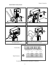
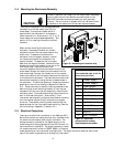
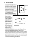
When remote mounting the electronics
enclosure, the support bracket can remain
attached to either the flow meter base or the
electronics. To separate the electronics
enclosure from the support bracket, remove
the two screws located on the back of the
support bracket. To separate the flow meter
base from the support bracket, remove the four
screws that mount the bracket to the top of the
flow meter base. Unscrew the electrical
connector between electronics enclosure and the flow
meter base. Remove the electronics enclosure from the
flow meter base. Connect the female end of the remote
electronics cable to the flow meter base and the male end
to the electronics enclosure. The electronics enclosure can
be mounted remotely by using the two threaded holes in
the enclosure. The size and spacing of these two holes are
specified on the outline drawing in Appendix 3 (Section
6.3). These holes may be used by inserting fasteners from
behind through a new mounting bracket or they may be
accessed from the front side by temporarily removing the
enclosure panel. This enables mounting the enclosure to a
wall or other solid structure. Alternatively, if the
instrument was originally configured as a bracket mounted
unit the bracket may be directly mounted to a support
structure. The bracket mounting holes locations are the
same as those for the flow meter base mounting. (See the
outline drawing in Appendix 3, Section 6.3.)
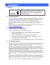
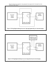
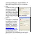
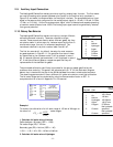
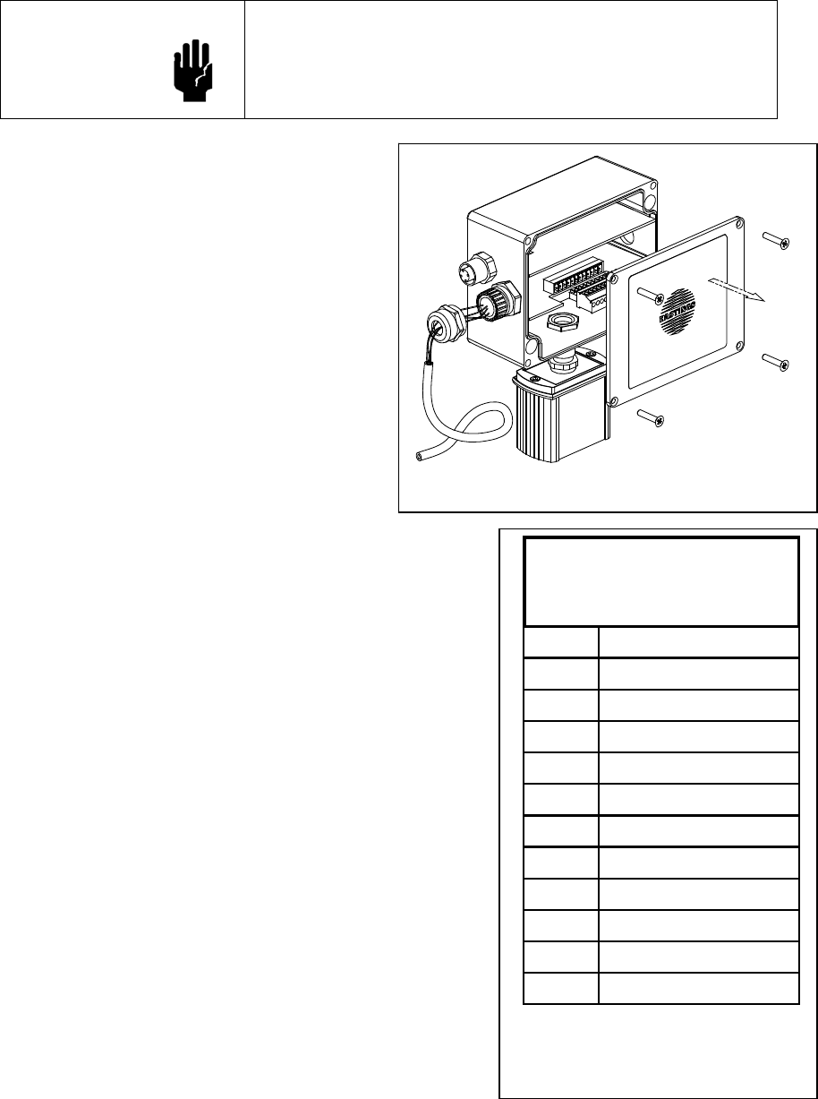
2.5. Electrical Connection
There are two electrical connectors on the Hastings 400-I
Series flow meters—an analog terminal strip (located within
the electronics enclosure) and a digital connector. The
analog connector provides for the power supply to the
meter along with analog signals and functions. As such, its
use is required for operation. The digital connector is used
for communications in either of RS232, RS485, or Ethernet
mode depending on the instrument’s configuration. The digital connector does not have to be
used if the meter is operated as an analog-only instrument.
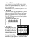
1 - Power Supply
2 + Power Supply
3- Flow Output
4+ Flow Output
5+ Auxiliary Input
6- Auxiliary Input
7 No Connection
8 Digital Common
9 Remote Zero
10 Alarm 1
11 Alarm 2
12 Alarm Common
Terminal Strip Pin-out
(Pins numbered right to left as
viewed from the front)
Figure 2-2 Electrical
connections for analog
inputs/outputs and power
Figure 2-1 Accessing the terminal strip