


- 8 -
2.5.2.2. Voltage output
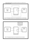
If the flow meter is configured for a voltage output, the signal will be available as a positive
potential on pin 4 relative to pin 3 of the terminal strip. Since these pins are galvanically
isolated, the signal cannot be read by an indicator between pin 4 and pin 1 of the terminal
strip. Pin 3 must be used as the return to properly read the output on pin 4. If an output that
is referenced to power supply common is desired then pins 3 and 1 must be connected. It is
recommended that these signals be transmitted through shielded cable, especially for
installations where long cable runs are required or if the cable is located near equipment that
emits RF energy or uses large currents.
Note: When the meter is configured with a voltage output it cannot generate a signal that is
more than a few mV below the zero volt value; therefore the 0-5 volt and 0-10 volt units are
limited in their ability to indicate a negative flow with the analog signal.
2.6. Digital Connection
The digital signals are available on a sealed female D-coded M12 connector that is designed for
use on industrial Ethernet connections. There are many options for connecting to the M12.
Hastings offers an 8 foot cable (stock# CB-RS232-M12) with a compatible male M12 connector to
a 9-pin D connector suitable for connecting the 400 I series instrument directly to the RS232
port on a PC. A cable to convert USB to RS232 9-pin is available from Hastings (stock# CB-USB-
RS232). Also, a 5 meter M12 male–male cable suitable for digital communications can be
purchased from Hastings (stock# CB-ETHERNET-M12). Other length cables are available from
Lumberg (#0985 342 100/5 M) or Phoenix. Converters from the M12 connector to a standard
modular Ethernet connector are available from Hastings or from Lumberg (#0981 ENC 100). A
compatible M12 connector suitable for field wiring can be acquired from Harting (21 03 281
1405) or Mouser (617-21-03-281-1405).
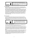
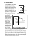
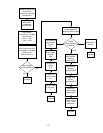
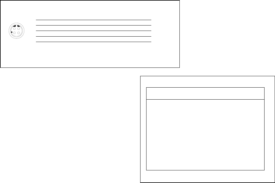
The pin-out for the digital connector is shown in Figure 2-5.
34
12
4
3
2
1
SHIELD
PINS
GROUND
TRANSMIT
RECEIVE
UNUSED
UNUSED
RS232
GROUND
ETHERNET
RD+
TD+
TD-
RD-
RX- (B)
TX- (B)
TX+ (A)
RX+ (A)
RS485
GROUND
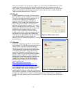
2.7. Digital Configuration
A Hastings 400-I Series flow meter is available
with one of three digital communications
interfaces, RS232, RS485, or Ethernet. Unless
specified differently at the time of ordering, the
flow meter is configured for RS232 operation. For
each interface, there are changes that can be
made to the configuration, either via software or
hardware settings. A brief overview of these is
included here. For more detailed information,
consult the Hastings 400 Series Software Manual.
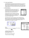
2.7.1. RS-232
The default configuration for the RS-232
interface is 19200 baud, 8 data bits, no–parity,
one stop bit. The baud rate is software
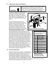
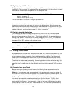
selectable and can be overridden by a hardware setting. Hardware settings for RS-232 and RS-
485 are enacted on 12 pin jumper field located on the left end of the top circuit board in the
Jumper
Enabled Disabled
1 RS485 RS232
2 Half Duplex Full Duplex
3 TX Terminated Unterminated
4 RX Terminated Unterminated
5 9600 Baud Software Selected
6 Addr = 99 Software Selected
Figure 2-6 Functions for digital jumper field
Figure 2-5 Digital connector pin-out