


- 1 -
General Information
1. General Information
1.1. Overview
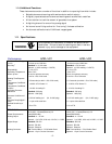
1.1.1. 400 Series Family
The Hastings 400 Series is a family of flow instruments which is specifically designed to meet
the needs of the industrial gas flow market. The “I” family in the 400 Series features an IP-65
enclosure which allows the use of the instrument in a wide variety of environments. The 400 I
products consist of four configurations: a flow meter, HFM-I-401, which has a nominal nitrogen
full scale between 10 SLM and 300 SLM and a corresponding flow controller, the HFC-I-403; a
larger flow meter, HFM-I-405, which ranges from 100 SLM to 2500 SLM, and a corresponding
flow controller, the HFC-I-407. These instruments are configured in a convenient in-line flow-
through design with standard fittings. Each instrument in the series can be driven by either a
+24 VDC power supply or a bipolar ±15 volt supply. The electrical connection can be made via
either a terminal strip located inside the enclosure or optionally through an IP-65 compatible
electrical connector. Also, these instruments include both analog and digital communications
capabilities.
1.1.2. 400 Series Meters
The Hastings HFM-I-401 and HFM-I-405 thermal mass flow meters are designed to provide very
accurate measurements over a wide range of flow rates and environmental conditions. The
design is such that no damage will occur from moderate overpressure or overflows and no
maintenance is required under normal operating conditions when using clean gases.
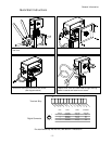
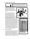
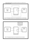
1.1.3. Measurement Approach
The instrument is based on mass flow sensing. This is accomplished by combining a high-speed
thermal transfer sensor with a parallel laminar flow shunt (see Figure 1-1). The flow through
the meter is split between the sensor and shunt in a constant ratio set by the full scale range.
The thermal sensor consists of a stainless steel tube with a heater at its center and two
thermocouples symmetrically located upstream and downstream of the heater. The ends of the
sensor tube pass through an aluminum block and into the stainless steel sensor base. With no
flow in the tube the thermocouples report the same elevated temperature; however a forward
flow cools the upstream thermocouple relative to the downstream. This temperature
difference generates a voltage signal in the sensor which is digitized and transferred to the
main processor in the electronics enclosure. The processor uses this real-time information and
the sensor/shunt characteristics stored in non-volatile memory to calculate and report the
flow.
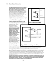
To ensure an inherently linear response to flow, both the thermal sensor and the shunt have
been engineered to overcome problems common to other flow meter designs. For example,
nonlinearities and performance variations often arise in typical flow meters due to pressure-
related effects at the entrance and exit areas of the laminar flow shunt. Hastings has designed
the 400 Series meters such that the flow-critical splitting occurs at locations safely downstream
from the entrance effects and well upstream from the exit effects. This vastly improves the
stability of the flow ratio between the sensor and shunt. The result of this design feature is a
better measurement when the specific gravity of the flowing medium varies, for instance due
to changes in pressure or gas type. Also, a common problem in typical flow meters is a slow
response to flow changes. To improve response time, some flow meter designs introduce
impurities such as silica gel. Alternatively, Hastings has designed the 400 Series sensor with
reduced thermal mass to improve the response time without exposing additional materials to
the gas stream.