


- 6 -
CAUTION
In order to maintain the environmental integrity of the
enclosure the power/signal cable jacket must have a diameter
of .157 - .315” (4 – 11 mm). The nut on the cable gland must
be tightened down sufficiently to secure the cable. This cable
must be rated for at least 85°C.
2.5.1. Power Supply
Ensure that the power source meets the requirements detailed in the specifications section.
Hastings offers several power supply and readout products that meet these standards and are
CE marked. If multiple flow meters or other devices are sharing the same power supply, it must
have sufficient capability to provide the combined maximum current.
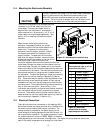
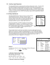
Power is delivered to the instrument through pins 1 and 2 of the analog terminal strip located
within the electronics enclosure (see Figure 2-1). As shown in the pin-out diagram Figure 2-2,
the positive polarity of the power supply is connected to pin 2 and the negative is connected to
pin 1. (For a unipolar power supply, pin 1 is power common and pin 2 is +24V. For a bipolar
±15V power supply, pin 1 is -15V and pin 2 is + 15V.) To allow for inadvertent reversal of the
power polarity, an internal diode bridge will ensure that the proper polarity is applied to the
internal circuitry. A green LED located next to the terminal strip will illuminate when the
meter is properly powered. The power supply inputs are galvanically isolated from all other
analog and digital circuitry.
2.5.2. Analog Output
The indicated flow output signal is found on pins 3 and 4 of the terminal strip as shown in
Figure 2-2. The negative output pin 3 is galvanically isolated from chasis ground and from the
power supply input common. The 400 Series meters can be configured to provide one of many
available current and voltage outputs; the standard 4 -20 mA or the optional 0 -20 mA, 0-5 Vdc,
1-5 Vdc, or 0-10 Vdc.
2.5.2.1. Current Loop Output
The standard instrument output is a 4 - 20 mA signal proportional to the measured flow (i.e. 4
mA = zero flow and 20 mA = 100% FS). An optional current output of 0 – 20 mA (where 0 mA =
zero flow and 20 mA = 100% FS) may be selected at the time of ordering.
If either current loop output has been selected, the flow meter acts as a passive transmitter. It
neither sources nor sinks the current signal. The polarity of the loop must be such that pin 4 is
at a higher potential than pin 3 on the flow meter terminal strip. Loop power must be supplied
with a potential in the range of 5-28 Vdc from a source external to the flow meter. The loop
supply can be the same supply as that for the instrument power or it can be an isolated loop
supply.
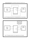
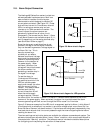
Figure 2-3 shows a typical setup using the same supply. This method requires a jumper from pin
2 to pin 4 on the terminal strip while connecting pin 3 to a wire that carries this signal to the
indicator (for example, a process ammeter, data acquisition system, or PLC board). To
complete the current loop, another wire carries the return signal from the flow indicator back
to the negative end of the input supply.(Alternatively, the loop current can be measured on
the “high potential side” by connecting the indicator between the pins 2 and 4 while
connecting pin 3 to pin 1.)
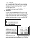
NOTE
When the meter is configured with milliamp output it
cannot generate a signal that is below the zero current
value; therefore the 0-20 mA unit is limited in its
ability to indicate a negative flow with the analog
signal.