


- 15 -
3.3.1. Digitally Reported Flow Output
The flow rate can be read digitally by sending an ascii “F” command (preceded by the address
for RS-485). The instrument will respond with an ascii representation of the numerical value of
the flow rate in the units of flow specified on the nameplate label.
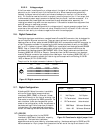
Example: A meter with RS-232 communications, calibrated for 500 slm FS N
2
Computer transmits: {F}
HFM flow meter replies: {137.5}
This is interpreted as 137.5 slm of nitrogen equivalent flow.
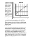
In most situations, the flow meter can measure beyond its range (i.e. a flow that exceeds the
full scale or a reverse flow) and report the value via the digital output. While the meter can
perform beyond its stated range, the accuracy of these values has not been verified during the
calibration process. Flows that exceed 160% of the nominal shunt range (S46 response) should
not be relied upon. See the software manual for further information.
3.3.2. Digitally Reported Analog Input
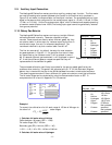
The flow meter can read the analog value present on pins 5 & 6 of the terminal strip (See
Section 2.9). This function is typically used to read the analog output from a nearby sensor
such as a pressure sensor or vacuum gauge. This value is spanned for the same range as the
analog output signal; it reads volts for flow meter configured for 0-5, 0-10 or 1-5 volt output
and milliamps for a flow meter configured for 0-20 or 4-20 milliamp output. The value is
accessed via the “S26” software query as shown below.
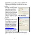
Example: A meter calibrated for 0-5 volt output and RS-232 communications.
Computer transmits: {S26}
HFM flow meter replies: {2.532}
This is interpreted as 2.532 volts.
3.4. Zeroing the Instrument
A proper zeroing of the flow meter is recommended after initial installation and warm-up. It is
also advisable to check the zero flow indication periodically during operation. Any uncertainty
at zero flow is an offset value which affects all subsequent flow readings. The frequency of
these routine checks depends on factors such as: the environmental conditions, the desired
level of accuracy, and the desire to measure low flow rates (relative to the meter full scale).
To achieve the most precise flow readings, the zeroing procedure is done while the meter is at
the expected operating conditions including temperature, line pressure, and gas type. This is
especially true for cases where the flow meter is operating at high pressure or with very dense
gas.
3.4.1. Preparing for a Zero Check
Before checking or adjusting the meter’s zero, the following three requirements must be
satisfied:
Warm-up – The instrument must be powered and in the operating environment for at least 30
minutes. Even though the meter will operate within a few minutes after power is applied, the
entire warm-up period is needed to establish a suitable zero reading.
No Flow – There must be an independent method to ensure that all flow through the
instrument has completely ceased before checking or adjusting the zero. Typically this is
achieved by closing valve downstream from the flow meter and waiting a sufficient time for
any transient flow to decay. This is especially critical for low flow units that have long piping
lengths before or after the flow meter. In such situations, it can require a significant settling
time for the flow cease and enable a precise zero.