Garmin G1000 Pilot’s Guide for Cessna Nav III
190-00498-07 Rev. A
50
FLIGHT INSTRUMENTS
SYSTEM
OVERVIEW
FLIGHT
INSTRUMENTS
EIS
AUDIO PANEL
& CNS
FLIGHT
MANAGEMENT
HAZARD
AVOIDANCE
AFCS
ADDITIONAL
FEATURES
APPENDICESINDEX
2.1 FLIGHT INSTRUMENTS
AIRSPEED INDICATOR
NOTE: Refer to the Pilot’s Operating Handbook (POH) for airspeed criteria and Vspeed values.
The Airspeed Indicator displays airspeed on a moving tape rolling number gauge. The true airspeed is
displayedinknotsbelowtheAirspeedIndicator.Thenumericlabelsandmajortickmarksonthemoving
tapeareshownatintervalsof10knots.Theminortickmarksonthemovingtapeareshownatintervalsof
veknots.Speedindicationstartsat20knots,with60knotsofairspeedviewableatanytime.Theindicated
airspeedisdisplayedinsidetheblackpointer.Thepointerremainsblackuntilreachingnever-exceedspeed
(V
NE
), at which point it turns red.
Figure 2-4 Red Pointer Showing
Overspeed (Model 172R)
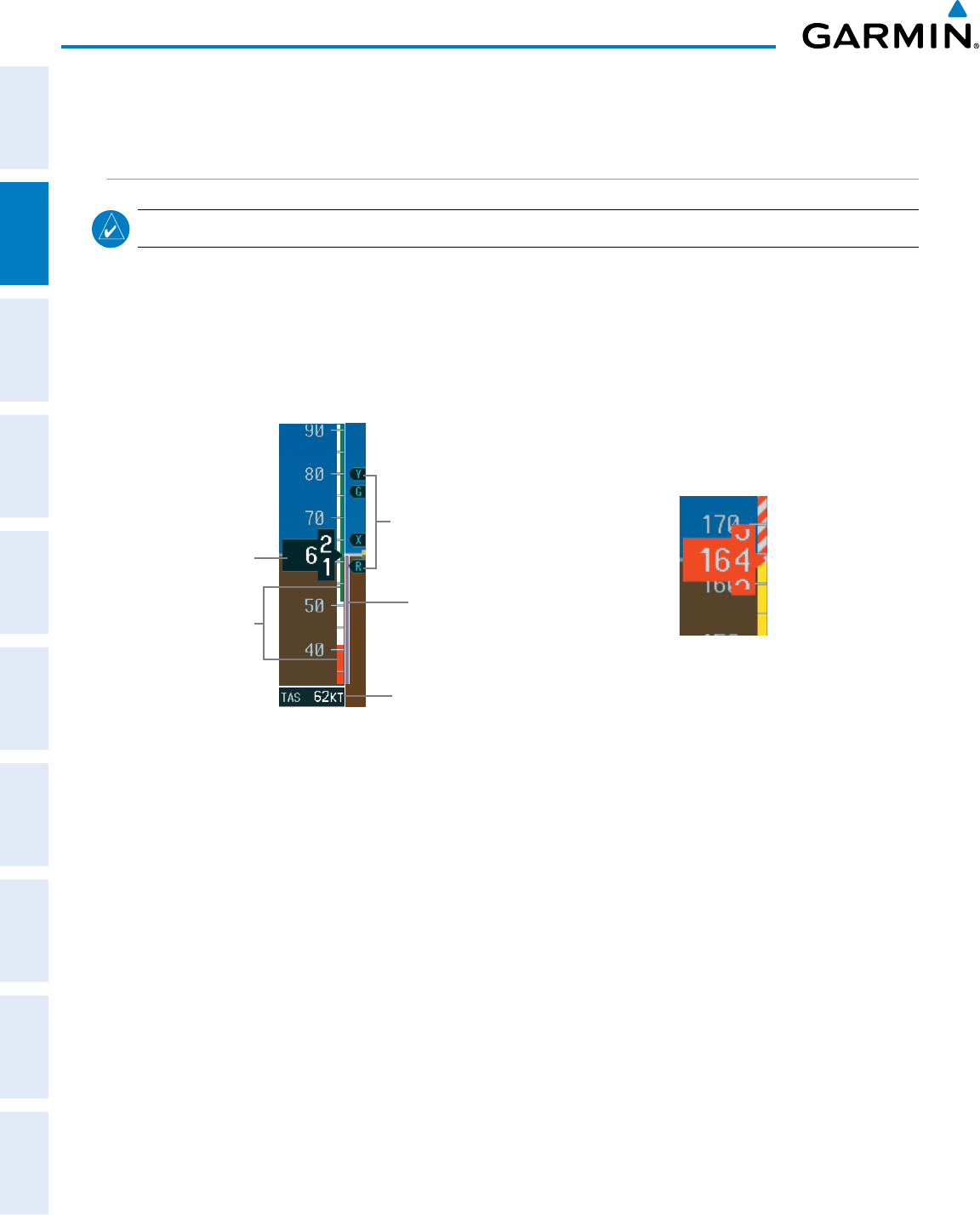
Figure 2-3 Airspeed Indicator (Model 182T)
Indicated
Airspeed
Vspeed
References
Speed
Ranges
True
Airspeed
Airspeed
Trend
Vector
Acolor-coded(white,green,yellow,andred)speedrangestripislocatedonthemovingtape.Thecolors
denote flaps operating range, normal operating range, caution range, and never-exceed speed (V
NE
).Aredrange
is also present for low speed awareness.
The Airspeed TrendVector is avertical,magentaline that appears to the right ofthecolor-coded speed
rangestripwhenairspeediseitheracceleratingordecelerating.Oneendofthemagentalineisanchoredto
the tip of the airspeed pointer while the other end moves continuously up or down corresponding to the rate
of acceleration or deceleration. For any constant rate of acceleration or deceleration, the moving end of the
line shows approximately what the indicated airspeed value will be in six seconds. If the trend vector crosses
V
NE
, the text of the actual airspeed readout changes to yellow. The trend vector is absent if the speed remains
constant or if any data needed to calculate airspeed is not available due to a system failure.


