


M100EU – OPERATIONS MANUAL TELEDYNE INSTRUMENTS
Addendum to M100E Manual - P/N 04515 GETTING STARTED
05944 Rev
B 7
DCN 5063 PRINTED DOCUMENTS ARE UNCONTROLLED
3. GETTING STARTED
3.1 UNPACKING THE M100EU
Unpack the M100EU as per the directions in Section 3.1 of the M100E Manual - P/N 04515, with the following
change. There are two redheaded shipping screws that hold down the PMT/Sensor assembly and must be
removed prior to operation. They are located along the base of the PMT housing adjacent to the chassis.
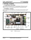
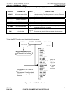
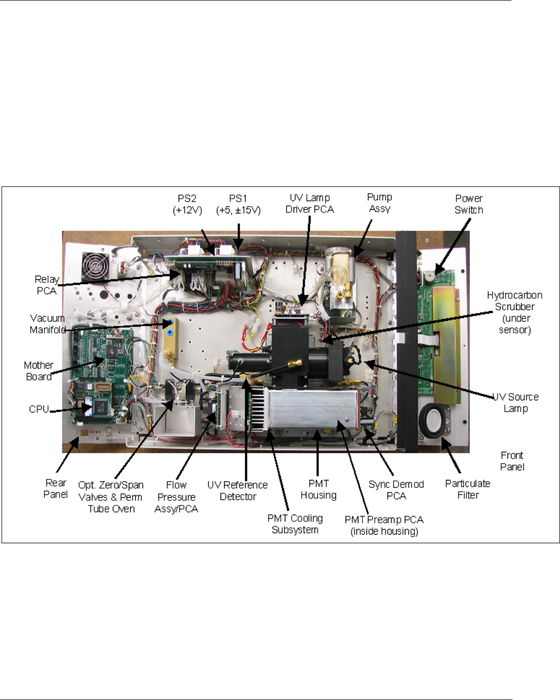
3.2 INTERNAL LAYOUTS
Figures 3-1 replaces Figure 3-9 in the M100E manual. The primary difference between the M100EU and M100E
layouts is the differences in the PMT Housing, the location of the PMT preamp PCA and the addition of a Sync
Demodulator PCA.
Figure 3-1: M100EU Internal Layout