


M100EU – OPERATIONS MANUAL TELEDYNE INSTRUMENTS
Addendum to M100E Manual - P/N 04145 THEORY OF OPERATION
10. THEORY OF OPERATION
The M100EU is a modified M100E. The primary differences are the way in which the PMT and UV reference
signals are acquired and processed. The M100EU has no shutter but rather employs synchronous
demodulation to capture the dark and light PMT and UV reference signals several times per second. A printed
circuit board, the Sync Demodulator, attached to the end of the PMT housing, on the sensor assembly, includes
circuitry that digitizes the PMT and UV reference signals and synchronizes the operation of the UV source with
these measurements. This method of signal processing minimizes the error that changing offsets could make in
an instrument that is designed to operate near its detection limit.
10.1 ELECTRONIC OPERATION
The following information is in addition to that contained in Section 10.2 of the M100E Manual - P/N 04145.
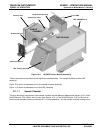
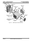
10.1.1 SENSOR MODULE
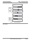
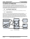
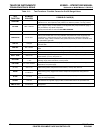
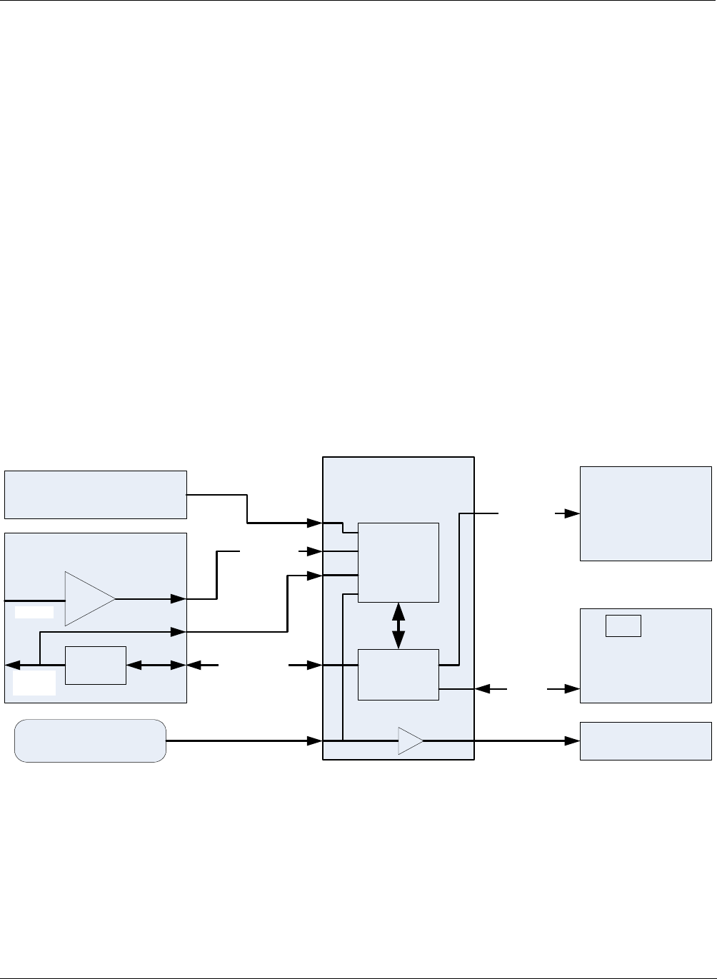
At the heart of the M100EU’s signal processing, illustrated in Figure 10-1 below, is the Synchronous
Demodulator PCA. The PCA is attached to the end of the PMT housing and serves to seal the end of the PMT
housing. The sync demodulator controls the operation of the UV Lamp driver, digitizes the analog output
signals from the PMT UV reference detector and PMT temperature sensor, controls the PMT cooler (TEC),
controls the PMT HV via a local I2C bus, and communicates with the analyzer’s CPU over the master I2C bus.
Digitized and processed data from the UV reference and PMT are passed to the analyzer’s CPU over the master
I2C bus and data for control of the PMT HV control DAC is passed from the CPU to the DAC on the PMT
preamp via the microcontroller on the Sync Demod board.
SYNC DEMOD PCA
(End of PMT Housing)
PMT Signal
UV REF PCA
(End of Sensor Module)
UV REF
Local I2C Bus
A/D
Converter
Micro
Controller
UV LAMP DRIVER
PCA
(Side of Sensor Assy)
Master
I2C Bus
PMT PREAMP PCA
(Inside PMT Housing)
8 bit DAC
PMT HV
Control
I2C
PMT IN
MOTHERBOARD
(Rear Panel)
CPU
PMT Temp Sensor
(Inside PMT Housing)
`
Lamp Sync
PMT Cooler
(End of PMT Housing)
PMT HV
Monitor
Figure 10-1: Sensor Block Diagram
05944 Rev B 23
DCN 5063 PRINTED DOCUMENTS ARE UNCONTROLLED