


M100EU – OPERATIONS MANUAL TELEDYNE INSTRUMENTS
Addendum to M100E Manual - P/N 04145 TROUBLESHOOTING & REPAIR
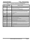
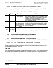
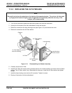
11.1.3 FAULT DIAGNOSIS WITH SYNC DEMOD PCA LEDS
There are four green Light Emitting Diodes (LEDs) on the bottom left side of the Sync Demodulator PCA. They
indicate various statuses and can be used to troubleshoot problems associated with the board.
Table 11-2: Relay PCA Status LED Failure Indications
Indicator Function Description Action
DS4 Watchdog Toggles on or off
every second
Steady on or off controller on PCA has crashed, PMT
temp. control still operates but PMT, REF and PMT Temp
voltages as shown in test functions will be XXXX. Press
reset button on sync demod to restart, if problem
continues check power supply voltages on PCA or PCA is
failing and must be replaced
DS3 I2C Activity Flashes each time
sync demod is polled
by instrument CPU
once every 1 to 1.5
seconds
Steady on or off indicates I2C bus failure check wiring
harness taking I2C to motherboard, another I2C device is
hanging bus, I2C transceiver on motherboard has failed,
or CPU has problem
DS2 A/D Status 1
DS1 A/D Status 2
Short frequent
flashes tracks timing
of A/D converter
Lack of flash indicates internal failure of A/D or firmware.
Press reset button on sync demod to restart, if problem
continues check power supply voltages on PCA or PCA is
failing and must be replaced
11.2 OTHER PERFORMANCE PROBLEMS
Please refer to Section 11.4 of the M100E manual, P/N 04515 for information.
11.3 ADDITIONAL REPAIR PROCEDURES
The following repair procedures are in addition to those listed in Section 11.6 of the M100E Manual - P/N 04145,
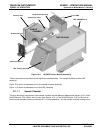
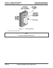
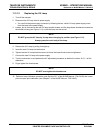
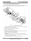
11.3.1 UV LAMP ADJUSTMENT AND/OR REPLACEMENT
There are two ways in which ambient conditions can affect the UV Lamp output and therefore the accuracy of the
SO2 concentration measurement. These are:
LAMP AGING
Over a period
of months, the UV energy will show a downward trend, usually 30% - 50% in the first 90 days, and
then a slower rate, until the end of useful life of the lamp. Periodically running the UV lamp calibration routine
(see Section 6.9.7 of the M100E Manual - P/N 04145) will compensate for this until the lamp output becomes too
low to function at all, 2-3 years nominally.
LAMP POSITIONING
05944 Rev B 29
DCN 5063 PRINTED DOCUMENTS ARE UNCONTROLLED