


TELEDYNE INSTRUMENTS
Model 100EU Instruction Manual
APPENDIX A - Version Specific Software Documentation
05928 Rev F.0B A-29
DCN 5063 PRINTED DOCUMENTS ARE UNCONTROLLED
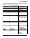
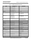
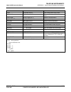
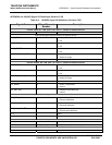
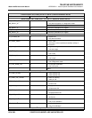
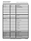
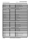
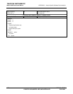
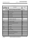
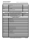
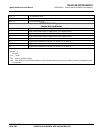
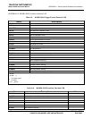
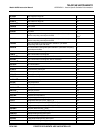
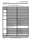
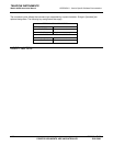
M100E MODBUS Register Map
MODBUS
Register Address
(dec., 0-based)
Description Units
MODBUS Floating Point Input Registers
(32-bit IEEE 754 format; read in high-word, low-word order; read-only)
0 PMT detector reading mV
2
1
Pre-amplified UV lamp intensity reading mV
4 UV lamp intensity reading mV
6 UV lamp ratio of calibrated intensity %
8 PMT electrical offset mV
10 UV lamp electrical offset mV
12 SO
2
slope for range #1 —
14 SO
2
slope for range #2 —
16 SO
2
offset for range #1 mV
18 SO
2
offset for range #2 mV
20
SO
2
concentration for range #1 during zero/span calibration, just
before computing new slope and offset
PPB,
PPM
2
22
SO
2
concentration for range #2 during zero/span calibration, just
before computing new slope and offset
PPB
24 SO
2
concentration for range #1 PPB
26 SO
2
concentration for range #2 PPB
28
12
SO
2
concentration for range #1, with O
2
correction PPB
30
12
SO
2
concentration for range #2, with O
2
correction PPB
32 Conc entration stability PPB
34 Stray light reading PPB
36 Reaction cell temperature
C
38
1
IZ S temperature
C
40 PMT temperature
C
42
1, 2
Sample flow cc/m
44 Sampl e pressure “Hg
46
2
Vacuum pressure “Hg
48 Internal box temperature
C
50 High voltage power supply output Volts
52 Diagnostic test input (TEST_INPUT_8) mV
54 Diagnostic temperature input (TEMP_INPUT_5)
C
56 Diagnostic temperature input (TEMP_INPUT_6)
C
58 Ground reference (REF_GND) mV
60 4096 mV reference (REF_4096_MV) mV
100
10
O
2
concentration %