preliminary
5
Part Names and Functions
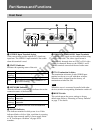
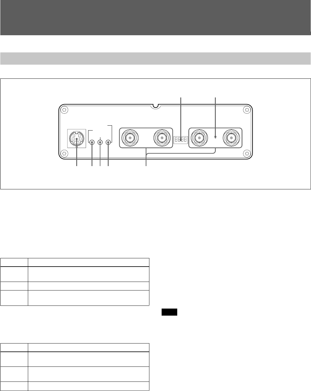
Front Panel
S VIDEO VIDEO 1
POWER
STATUS
NETWORK
VIDEO 2
75Ω OFF
4321
75Ω ON
VIDEO 3 VIDEO 4
1 S VIDEO Input Terminal (4 pins)
Video sources that provide separate Y/C signals are
input here. The VIDEO 1 input terminal is not usable
when this terminal is used.
2 STATUS Indicator
Indicates the operating status of the unit.
3 NETWORK Indicator
After the self-test is complete, this indicator shows the
connection status of the network.
4 POWER Indicator
This indicator remains lit while power is on. If this
indicator blinks or fails to light, a problem is occurring
with the video network station’s power supply. Refer
to “If You Suspect a Problem” on page 40 for
remedies.
5 VIDEO 1 to VIDEO 4 BNC Input Terminals
Composite video signals can be connected here using
coaxial video cable. The video signal format is
automatically detected when an NTSC or PAL video
source is connected. However, the VIDEO 1 and S
VIDEO terminals cannot both be used at the same
time.
6 75-Ω Termination Switches
The termination resistance of each VIDEO input
terminal can be set on or off with these switches.
When the unit is shipped from the factory, all
termination switches are ON.
Note
When this server is connected in parallel with other
devices, turn the corresponding termination switch off.
7 RESET Switch
This switch returns the server settings to factory
default state. Refer to “Resetting to Factory Defaults”
on page 37 for details.
Color
Orange
(blinking)
Green
Red
Server Status
The self-test is executing after turning power on.
Normal operation
Fault. Refer to “If You Suspect a Problem” on
page 40 for remedies.
Color
Orange
(blinking)
Green
(blinking)
Red
Network Connection Status
A 10-Mbps Ethernet connection has been
established.
A 100-Mbps Ethernet connection has been
established.
No network connection could be established.
1234 5
67


