


preliminary
Operation
34
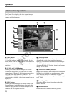
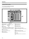
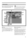
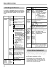
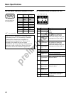
3 Display Partition Buttons
Clicking one of these icons selects the image monitor
layout. The icons are applicable to the A IMAGE
output of the HSR-1/1P/2/2P, and are functional when
the [A] button qh is selected, or when the [A/B] button
qf and the [A] button 4 are selected. The icons
appear as follows when enabled for use.
The HSR View can display four to 16 partitions. The
system administrator determines which camera is
assigned to each display partition.
4 [A] and [B] Buttons
These buttons are enabled when [A/B] button qf is
selected. Clicking the [A] button causes the screen
control buttons to affect the [A] image, and clicking
the [B] button causes the screen control buttons to
affect the [B] image.
5 Paging Buttons
If the screen partitions span multiple pages, click these
buttons to change pages.
6 Users Logged On
Shows the number of users logged on to the video
network station.
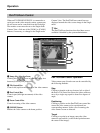
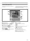
7 [HOME] Button
Clicking this button returns the video camera to its
preset (home) position. Its action applies to the image
at which the pan/tilt control bar is displayed.
8 [PRESET] Drop-Down List
Select a preset camera position by name from this list
to set the camera to that fixed position (previously set
by the system administrator). Selecting from this list
while the display is partitioned causes the screen to
switch to a single image showing the selected video
camera.
9 [Camera] Button
Clicking this button changes to the Camera View.
0 [Admin] Button
Clicking this button displays the “Admin overview”
page, where video network station settings and
management can be performed. Access to this page is
normally restricted to the administrator.
qa Connection Status
Shows the type of HSR unit (HSR-1/1P or HSR-2/2P)
connected to the video network station. If the
connected HSR-1/1P/2/2P is not turned on or
communicating properly, [DISCONNECT] is
displayed.
qs Date and Time
This is current date and time. The system administrator
determines whether the date and time are displayed.
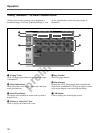
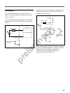
qd Pan/Tilt/Zoom Control Bars
Use to control video camera pan, tilt and zoom.
The bars are displayed and enabled in the following
cases:
• When a video camera capable of pan/tilt/zoom
operation is selected by the numbered buttons.
• When a video camera capable of pan/tilt/zoom
operation is selected by the [B] button qg.
• While output of the A IMAGE and B IMAGE is
displayed by the [A/B] button qf and a video camera
capable of pan/tilt/zoom operation is selected by the
[A] or [B] button 4.
Refer to “Pan/Tilt/Zoom Control” on page 28 for
details of control bar operations.
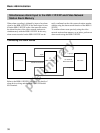
qf [A/B] Button
Clicking this button displays A IMAGE and B IMAGE
from the HSR-1/1P/2/2P, on a split screen.
qg [B] Button
Clicking this button displays the B IMAGE from the
HSR-1/1P/2/2P.
qh [A] Button
Clicking this button displays the A IMAGE from the
HSR-1/1P/2/2P.
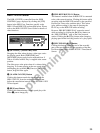
qj [CTR] Button
Clicking this button displays the “HSR CONTROL”
page in a new window, for controlling the HSR-1/1P/
2/2P. Refer to “HSR-1/1P/2/2P Control” below for
details.
qk [SEQ] Button
Clicking this button controls the automatic image
switching function of the HSR-1/1P/2/2P, in which the
image from each camera is displayed sequentially,
switching from one camera to the next at preset
intervals. Click the button again to cancel.