


preliminary
43
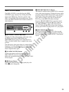
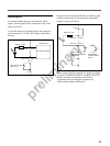
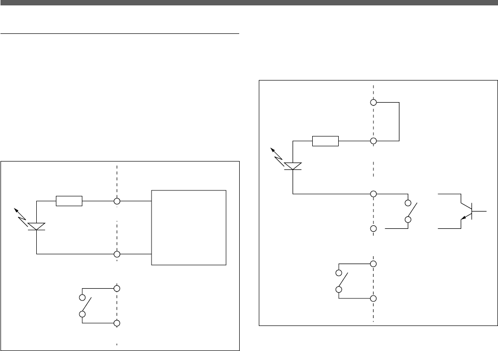
Alarm Inputs
Four photocoupler inputs are provided for alarm
inputs. Alarm signals can be connected to any of the
inputs as follows.
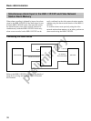
To use the electrically isolated inputs, the connected
device must have 5 to 20-V DC output, connected as
follows.
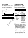
If an alarm device has mechanically switched or open-
collector outputs that do not need to be electrically
isolated, connect as follows.
• Refer to the respective manuals for details on setting
up the EVI-D30/D31/G20/G21 and HSR-1/1P/2/2P.
• Please note that specifications and external
appearance may be changed for purposes of
improvement without notification.
Inside server←→Outside server
Approx. 4.7 kΩ
Alarm Device
5 to 20V DC Output
Max. 24V AC/DC
@100 mA
Pins 3, 5, 11 and 13
+
Pins 4, 6, 12 and 14
–
Pin 15
Pin 16
Inside server←→Outside server
Approx. 4.7 kΩ
Pins 3, 5, 11 and 13
Pins 4, 6, 12 and 14
Pin 9
Pin 10
Mechanically switched
output device
Mechanically
switched output
device