


preliminary
Basic Specifications
42
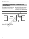
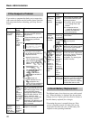
RS-232 Serial Interface Terminal Pin Out
5 4 3 2 1
9 8 7 6
• NC = no connection
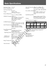
This is a Class A Information Technology Device
conforming to the VCCI (Voluntarily Controlled
Communication Interference) standards for
information processing devices. This device is
designed to be suitable for use in a home
environment, but it may interfere with reception if
used near a radio or television. Please follow the
instructions in the users manual for proper use.
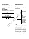
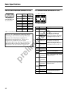
I/O Terminal Block Connector Pin Out
87654321
ABC4A4C3A3--
161514131211109
RELAYC2A2C1A1–+
Connector width must
not exceed 32 mm.
Pin No.
1
2
3
4
5
6
7
8
9
COM1
function
NC
-RXD
-TXD
RTS
GND
DSR
RTS
NC
NC
COM2
function
CD
-RXD
-TXD
DTR
GND
DSR
RTS
CTS
RI
Pin
1
2
3
4
5
6
7
8
9
10
11
12
13
14
15
16
Function
Reserved
Reserved
Input 3
Photocoupler
(+)
Input 3
Photocoupler
(–)
Input 4
Photocoupler
(+)
Input 4
Photocoupler
(–)
Reserved
Reserved
Photocoupler
power
Input 1
Photocoupler
(+)
Input 1
Photocoupler
(–)
Input 2
Photocoupler
(+)
Input 2
Photocoupler
(–)
Relay Switch
Relay Switch
Description
Do not use
Photocoupler input 3: the sash
and contacts are electrically
isolated, so input can be an
external DC voltage or DC power
input/output from pins 9 and 10.
Photocoupler input 4: the sash
and contacts are electrically
isolated, so input can be an
external DC voltage or DC power
input/output from pins 9 and 10.
Do not use
Power for Photocouplers
Input 1 Photocoupler input. Same
as Input 3 above.
Input 2 Photocoupler input. Same
as Input 3 above.
The relay switch is electrically
isolated from the sash and
connectors.