


Tracer® SX5 42 Part No. 1110550
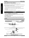
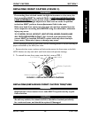
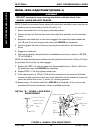
WHEEL LOCK ADJUSTMENT(FIGURE 4)
WARNING
DO NOT attempt to stop a moving wheelchair with the wheel locks.
WHEEL LOCKS ARE NOT BRAKES.
NOTE: If wheels are pneumatic, before adjusting the wheel lock assemblies, ensure that the tires
are inflated to the recommended psi on the side wall of tire.
1. Ensure the wheel lock is in the open (unlocked) position.
2. Loosen the bolt and locknut that secure the wheel lock assembly to the wheelchair
frame.
3. Reposition the wheel lock so that when engaged, the wheel lock shoe embeds the
tire 1/8-inch (3/16-inch for pneumatic tires) and HOLDS the wheelchair.
4. Securely tighten the bolt and locknut securing the wheel lock to the wheelchair
frame.
5. Engage the wheel lock.
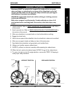
6. Measure the distance the wheel lock is embedded into the tire as shown in DETAIL
"A" of FIGURE 4.
NOTE: Any wheel lock adjustment should embed the wheel lock shoe at least 1/8-inch (3/16-inch
for pneumatic tires) into the tire when engaged.
7. Repeat the STEPS 1-6 until the wheel lock shoe embeds the tire 1/8-inch (3/16-inch
for pneumatic tires) and HOLDS the wheelchair.
8. Repeat STEPS 1-7 for the opposite wheel lock.
9. If the measurement of 1/8-inch (3/16-inch for pneumatic tires) cannot be achieved,
remove the bolt and locknut that secure the wheel lock to the wheelchair frame and
mount the wheel lock in one (1) of two (2) mounting positions.
10. Repeat steps 1-9 until the wheel lock HOLDS the wheelchair. If the correct mea-
surement still cannot be achieved, contact a qualified technician.
ANTI-TIPPERS/WHEEL LOCKSSECTION 8
ANTI-TIPPERS/WHEEL LOCKS
Wheel Lock
Handle
Bolt and Locknut
Mounting Positions
Wheel Lock
Shoe
Tire
Rear
Wheel
FIGURE 4 - WHEEL LOCK ADJUSTMENT
Wheel
Lock
DETAIL "A" - WHEEL LOCK SHOE
ENGAGEMENT
1/8-inch (3/16-inch
pneumatic tires)
Tire
Wheel Lock
Shoe