


Tracer® SX5 24 Part No. 1110550
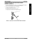
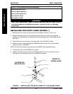
HEEL LOOP REPLACEMENT (FIGURE 3)
1. Pull the cam lock lever to UP (UN-
LOCKED) position.
2. Push IN the release buttons and re-
move the lower footrest assembly.
3. Remove the mounting screw, spacer
and locknut that secure the heel loop
to the footrest.
4. Remove EXISTING heel loop from
slide tube.
5. Install NEW heel loop onto slide tube.
6. Install the mounting screw, spacer and
locknut to secure the heel loop to the
footrest. Tighten until the spacer is secure.
7. Insert the lower footrest assembly into the upper footrest assembly to desired
height.
8. Ensure that the release buttons fully protrude from holes on both sides of the upper
footrest support.
9. Rotate cam lock lever DOWN to LOCKED position.
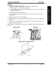
SECTION 3 FRONT RIGGINGS
FRONT RIGGINGS
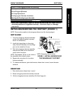
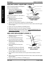
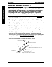
FOOTREST HEIGHT ADJUSTMENT (FIGURE 2)
NOTE: This procedure applies to the swingaway
footrest and eleveating legrest.
1. Remove the swingaway footrest
assembly. Refer to INSTALLING/
REMOVING THE SWINGAWAY
FOOTREST in this section of the
manual.
NOTE: Lay the assembly on a flat surface to
simplify this procedure.
2. Pull the cam lock lever to UP (UN-
LOCKED) position.
3. Push IN the release buttons and
reposition the lower footrest assembly to the desired height.
4. Ensure that the release buttons fully protrude from holes on both sides of the upper
footrest support.
5. Rotate cam lock lever DOWN to LOCKED position.
6. Repeat this procedure for the other footrest, if necessary.
7. Reinstall the swingaway footrest assembly. Refer to
INSTALLING/REMOVING THE
SWINGAWAY FOOTREST in this section of the manual.
FIGURE 3 - HEEL LOOP
REPLACEMENT
Spacer
Locknut
Cam Lock Lever
Heel Loop
Slide Tube
Mounting Screw
Lower
Footrest
Assembly
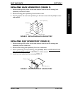
Footrest
Upper Footrest Support
Lower Footrest Assembly
Cam Lock
Lever
FIGURE 2 - SWINGAWAY
FOOTREST HEIGHT
ADJUSTMENT
Release Button
Adjustment
Holes
NOTE: Swingaway footrest shown.