SECTION 8—ANTI-TIPPERS/WHEEL LOCKS
Part No. 1076155 81 9000 Series
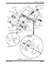
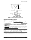
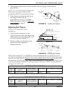
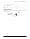
3. Measurethedistancebetweenthebottomoftheanti‐tipperwheelsandthe
ground/floor.
NOTE:A1½to2‐inchclearancebetweenthe
bottomoftheanti‐tipperwheelsandthe
ground/floorMUSTbemain tainedatalltimes.
4. Ifthedistancebetweenthebottomof
anti‐tipperwheelsandthe
ground/floorisnot1½to2‐inches,
adjustanti‐tippers.RefertoAdjusting
Anti‐Tippersonpage 81.
FIGURE 8.1 Installing Anti-Tippers
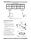
Adjusting Anti-Tippers
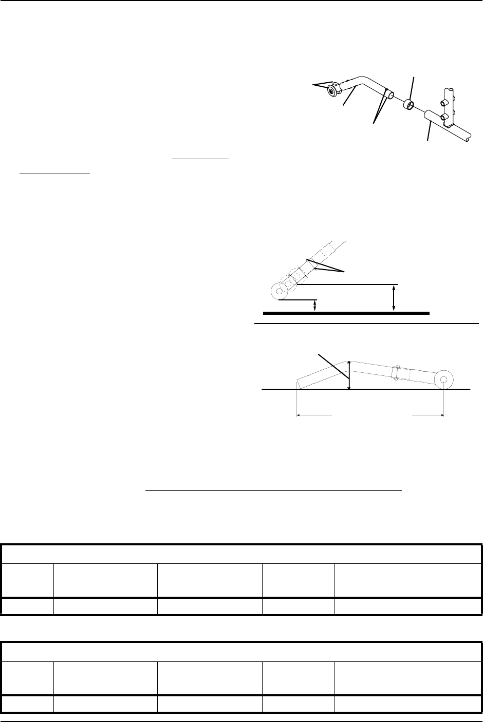
NOTE:Forthisprocedure,referto
FIGURE 8.2.
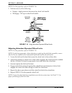
1. Pressthereleasebuttonsonthe
wheeledportionoftheanti‐tipperand
slideitupordowntoachievethe1‐1/2
to2‐inchclearance(Detail“A”).
2. Checktomakesurethattherelease
buttonsarefullyengagedin
adjustmentholes.
FIGURE 8.2 Adjusting Anti-Tippers
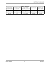
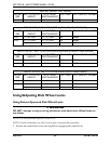
NOTE:RefertoDetail“B”inFIGURE 8.2andtothefollowingchartstoensurethecorrect
anti‐tipperisinstalledonthewheelchair.Seat‐to‐floorheightsareapproximatedependingonfront
castersizeandtype.Refer toChangingSeat‐to‐FloorHeight/Seat‐to‐FloorAngle
onpage 29for
anexplanationofframetimes.Anti‐Tipperlengthmeasurementistakenwiththeextensiontube
inthelongestpositionavailable.Theanti‐tipperheightmeasurementMUSTbetakenwiththe
anti‐tipperonaflatsurface.
Anti-Tipper
Wheels
Anti-Tipper
Release Buttons
Rear Frame
Tubing
Anti-Rattle
1½ inches
Release Buttons
2 inches
Anti-Tipper
Length
Anti-Tipper
Height
DETAIL “B”
DETAIL “A”
9000 XT (SUPER LOW FRAME)
CASTER
SIZE
SEAT-TO-FLOOR
HEIGHT
ANTI-TIPPER
LENGTH/HEIGHT
ON CHAIR OFF CHAIR KIT NUMBER
6-inch 13½ and 14½ inches 10½ / 2-inches 1360SH 1064520
9000 XDT (ADULT TALL FRAME)
CASTER
SIZE
SEAT-TO-FLOOR
HEIGHT
ANTI-TIPPER
LENGTH/HEIGHT
ON CHAIR OFF CHAIR KIT NUMBER
8-inch 17½ and 19½ inches 11-5/8 / 2-3/4-inches 1360A 1058752


