


Instruction Manual
760008-A
September 2001
4-6 Maintenance and Service Rosemount Analytical Inc. A Division of Emerson Process Management
Model NGA 2000 TO2
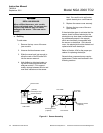
4-4 FLOW SENSOR REPLACEMENT
See Figure 1-2 for Flow Sensor location. To
replace Flow Sensor, remove all connecting
hardware and undo connections to the sample
line. The Flow Sensor is mounted to the Sen-
sor Assembly mounting plate by two screws.
Be sure to install the new Flow Sensor with
the flow indication toward the outlet.
4-5 ELECTRONIC COMPONENTS
a. Fuses
Remove power to the Analyzer Module
prior to fuse replacement. To replace the
Power Fuse, locate the fuse cover on the
front panel of the Analyzer Module, as
shown partially in Figure 2-4. Push and
turn the fuseholder cover 1/4 turn coun-
terclockwise. Remove and replace the
fuse as required. There are no other
fuses in the Analyzer Module.
b. Printed Circuit Boards
All three printed circuit boards can be re-
placed, if necessary. Refer to Figure 1-2
for location of the Power, Network and
Computer Boards.
To remove any PCB, disconnect the as-
sociated cables first. Tag each connector
and its location before disconnecting any
wiring. This helps in reassembly. The
Power board and Computer board are lo-
cated on a common bracket.