


Instruction Manual
760008-A
September 2001
Rosemount Analytical Inc. A Division of Emerson Process Management Installation 2-1
Model NGA 2000 TO2
SECTION 2
INSTALLATION
WARNING.
Before starting to install this equip-
ment, read the Safety Summary in
the Preface section of this manual.
Failure to follow the safety instruc-
tions could result in serious injury or
death.
2-1 UNPACKING
If the Trace Oxygen (TO2) Analyzer Module is
received as a separate unit, carefully examine
the shipping carton and contents for signs of
damage. Immediately notify the shipping car-
rier if the carton or contents is damaged. Re-
tain the carton and packing material until all
components associated with the TO2 Ana-
lyzer Module are operational.
2-2 ELECTROLYTE
Before installation of the TO2 Analyzer Mod-
ule, electrolyte must be added to the Sensor.
Follow the procedure described in Section 2-
2a.
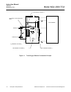
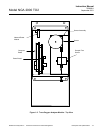
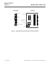
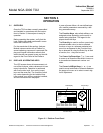
After addition of electrolyte, locate the ana-
lyzer module on an appropriate mounting
surface and connect the network cable to ei-
ther the NETWORK 1 or NETWORK 2 con-
nection on the Analyzer Module, and the
NETWORK connection on the Platform net-
work I/O port. (See Figure 2-1 and Figure
2-4.)
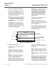
a. Electrolyte Addition
Before adding electrolyte to the Sensor, it
is recommended to check the Sensor for
possible leakage caused by damage in
shipment. To check the Sensor for leak-
age, remove the top cover of the Analyzer
Module and locate and remove the 5
mounting screws which hold the Sensor
Assembly (Sensor, flow meter, plumbing,
inlet/outlet fittings) to the module (see
Figure 4-1). Be careful not to lose these
screws as they have metric threads.
Carefully lift out the Sensor assembly and
remove from the analyzer module. Place
on a flat surface and remove the black
Sensor cover by unscrewing counter-
clockwise.
Add distilled or deionized water to the
Sensor to the maximum level indication
on the Sensor reservoir. Let Sensor
stand for approximately 15 minutes and
check for leaks around the base of the
reservoir, and at the seams and corners.
If a leak is found, contact the factory be-
fore proceeding. Drain the Sensor.
Fill the Sensor with one bottle of electro-
lyte supplied with the analyzer module.
Use the entire contents of the bottle.
NOTE
Do not add water. The volume and
concentration of the bottled electrolyte
is pre-measured.
Reinstall the black Sensor cover and
carefully reinstall the Sensor Assembly
inside the Analyzer Module. Do not tilt
the Sensor Assembly excessively as
electrolyte may leak out.
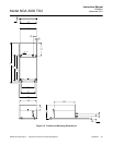
2-3 LOCATION
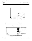
(See Figure 2-2) The TO2 Analyzer Module
comes standard with mounting ears for easy
installation on flat, horizontal surfaces. Install
the TO2 Analyzer Module in a clean, weather-
proofed, vibration-free location free from ex-
treme temperature variations and moisture.
For best results, install the instrument near
the sample stream to minimize sample trans-
port time.
Operating ambient temperature is 0 °C to 45
°C (32 °F to 81 °F). Temperature change
should not exceed 10 °C (18 °F) per hour.