


Instruction Manual
760008-A
September 2001
Rosemount Analytical Inc. A Division of Emerson Process Management Maintenance and Service 4-3
Model NGA 2000 TO2
b. Electrolyte Replacement
Before replacing the electrolyte, be sure
to turn off and disconnect all gas connec-
tions to the analyzer module. Turn off or
disconnect the power to the analyzer
module.
To replace the Sensor electrolyte:
CAUTION.
CAUSTIC LIQUID
Electrolyte is a caustic solution. Re-
view the Material Safety Data Sheet in
the rear of this manual.
1. Remove the Analyzer Module from
its mounting location and place on a
sturdy work surface. Be careful not
to tilt the module from its horizontal
position as the Sensor contains liq-
uid that can spill.
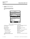
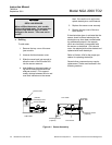
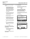
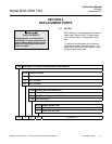
2. Remove the cover of the Analyzer
Module and locate the 5 mounting
screws that hold the Sensor As-
sembly onto the Analyzer Module
chassis (see Figure 4-1). Remove
the 5 screws and retain. Do not lose
the screws - they have metric
threads.
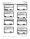
3. Disconnect the Sensor signal con-
nector (J5) and the Flow Sensor
connector (J6) from the power
board.
4. Remove the complete Sensor As-
sembly from the Analyzer Module.
5. Remove the black sensor cover and
invert the Sensor Assembly over a
suitable receptacle.
6. Flush the Sensor twice with deion-
ized water. Dispose of the dis-
carded electrolyte and rinse water in
accordance with National, Federal,
State and Local regulations.
7. Refill the Sensor with electrolyte as
instructed in Section 4-2b.
8. Reinstall the Sensor Assembly and
reconnect J5 and J6 to the power
board.
c. Sensor Replacement
If the Sensor cannot be regenerated by
the addition of water or the replacement
of electrolyte, or if the Sensor shows
signs of leakage, it may be necessary to
replace the Sensor. Obtain a replacement
sensor from the factory. Prior to installa-
tion of a new Sensor, perform the leak
check described in Section 4-2d.
To replace the Sensor:
1. Remove the Sensor Assembly and
remove the electrolyte as described
in Section 4-2b.
2. Reinstall the black sensor cover to
catch any residual electrolyte.
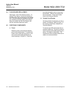
3. Invert the Sensor Assembly and lo-
cate the four (4) mounting screws
which hold the Sensor to the Sensor
Assembly mounting plate. Remove
and retain the four screws.
4. Install replacement Sensor in re-
verse order.
5. Check Sensor for leaks and add
electrolyte as described in Section
3-5d.
6. Reinstall Sensor Assembly in Ana-
lyzer Module and reconnect J5 and
J6 to the power board.
After installation of new Sensor, it will be
necessary to load new linearization data
as described in Section 4-3.
d. Sensor Lleak Check
Before adding electrolyte to the Sensor, it
is recommended to check the Sensor for