


Instruction Manual
760008-A
September 2001
Rosemount Analytical Inc. A Division of Emerson Process Management Operation 3-31
Model NGA 2000 TO2
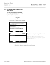
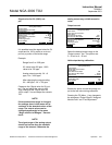
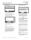
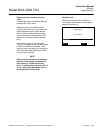
Choose signal…
Brings up menu shown below.
Choose desired source module for the
relay output number (1-3) being config-
ured.
The list of modules will depend on the in-
stalled modules.
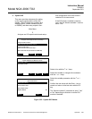
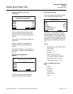
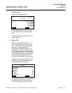
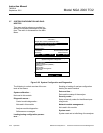
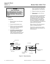
e. System DIO
Selecting “System DIO module…” from
the “System & Network I/O Module Con-
trols” menu (Figure 3-25) provides sub-
menus for setting up the output
configurations of the DIO signals. The
DIO board is comprised of 8 digital inputs
and 24 digital outputs. Functions of sup-
ported analyzer modules can be attached
to each input and a signal to each output.
Further detailed information about the
DIO board is contained in its own manual.
If there is no DIO module installed in the
analyzer, a corresponding message will
be displayed instead of the menu.
For detailed information on the installation
and setup of the DIO module, see the
NGA 2000 Platform manual p/n 760006.
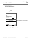
TO2 37.50 ppm
Measure
Back…
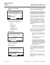
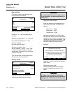
-- Choose Signal --
Function control
Maintenance request
Failure
Cal. In progress
Zero in progress
Span in progress
Zero failed
Span failed
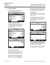
TO2 37.50 ppm
Measure
Back…
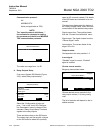
-- System DIO --
Input number: 1
Output number: 1
Choose module…
Choose signal…
Invert signal: No
Module status: ???
Slot ID: ???
Signal name: ???
Signal level: 000.0
Signal comes from: ???