


Instruction Manual
760008-A
September 2001
Rosemount Analytical Inc. A Division of Emerson Process Management Contents iii
Model NGA 2000 TO2
LIST OF ILLUSTRATIONS
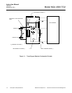
Figure 1-1. Trace Oxygen Detector Coulometric Principle..............................................................1-2
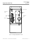
Figure 1-2. Trace Oxygen Analyzer Module - Top View .................................................................1-3
Figure 2-1. Analyzer Module Interconnection with Instrument Platform .........................................2-4
Figure 2-2. Outline and Mounting Dimensions................................................................................2-5
Figure 2-3. Back Panel Connections...............................................................................................2-6
Figure 2-4. Trace Oxygen Analyzer Front Panel.............................................................................2-6
Figure 3-1. Platform Front Panel .....................................................................................................3-1
Figure 3-2. The Display Screen.......................................................................................................3-2
Figure 3-3. Changing Variables.......................................................................................................3-3
Figure 3-4. Function Confirmation...................................................................................................3-3
Figure 3-5. Measure Mode Display .................................................................................................3-4
Figure 3-7. Module Manufacturing Data Displays ...........................................................................3-5
Figure 3-8. Startup Display..............................................................................................................3-6
Figure 3-9. Initiate Quick Start.........................................................................................................3-7
Figure 3-10. Analyzer Channel Status .............................................................................................3-8
Figure 3-11. Single Component Display............................................................................................3-9
Figure 3-12. Multi Component Display..............................................................................................3-10
Figure 3-13. Basic Controls and Setup .............................................................................................3-11
Figure 3-14. Display Controls............................................................................................................3-12
Figure 3-15. Expert Controls and Setup............................................................................................3-13
Figure 3-16. Calibration – Gas Scale Factor.....................................................................................3-15
Figure 3-17. Span Calibration............................................................................................................3-16
Figure 3-18. Alarms ...........................................................................................................................3-17
Figure 3-19. Ranges..........................................................................................................................3-18
Figure 3-20. Measurement Display Configuration.............................................................................3-19
Figure 3-21. Concentration Measurement.........................................................................................3-20
Figure 3-22. Flow Measurement........................................................................................................3-22
Figure 3-23. Temperature Measurement ..........................................................................................3-23
Figure 3-24. System & Network I/O Module Controls .......................................................................3-24
Figure 3-25. System SIO Module ......................................................................................................3-25
Figure 3-26. System Configuration and Diagnostics.........................................................................3-32
Figure 4-1. Sensor Assembly ..........................................................................................................4-2