Instruction Manual
IM-106-4050 Original Issue
March 2006
1-3
OxyBalance Oxygen Display
and Averaging System
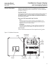
Physical Description Aside from the PanelView Plus 600, the OxyBalance system consists of
iadditional components mounted on three DIN rails. The main components
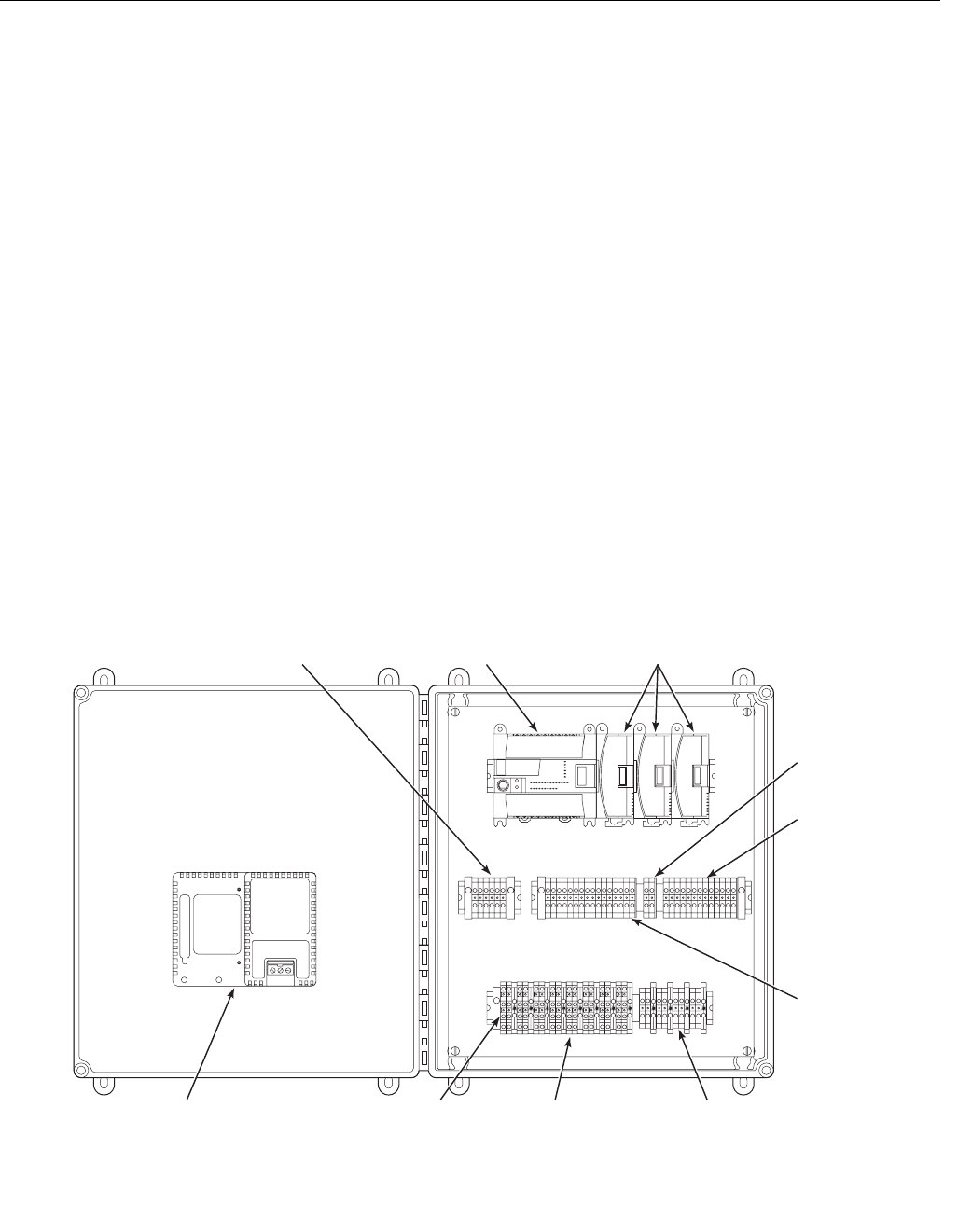
are shown in Figure 1-2.
PanelView Plus 600
The PanelView Plus 600 is the touch screen interface located on the front of
the OxyBalance system, all probe readings and averages are displayed
through this interface. There is also a power cord and communications cord
that connect to this module.
MicroLogix 1200 Programmable Logic Controller
PLC
The PLC process the raw data received by the OxyBalance. The
processed data is transmitted to the PanelView Plus 600, where it is
displayed on the touch screen interface.
I/O Modules
Also known as the expansion I/O, these modules act as part of the
controller system and are located on the right side of the PLC unit.
Input Terminals
This row of terminals receives the 4-20 mA signals from the O
2
probes.
Figure 1-2. OxyBalance Components
DCOMM
COMM0
FORCE
FAULT
RUN
POWER
OUT
47
IN
0123 5689
47
0 123568 9101112 13
1
0
4
3
2
0
1
0
1
3
4
3
4
22
7
6
5
5
6
7
5
6
7
38370016
PanelView
Plus 600
MicroLogix 1200
Programmable
Logic Controller
I/O Modules
Input
Terminals
Output
Terminals
Signal Pass
Through Terminals
Failure/
Warning
Terminals
Power
Terminals
In Cal
Terminals
PLC
Failure
Terminals


