


Instruction Manual
IM-106-4050 Original Issue
March 2006
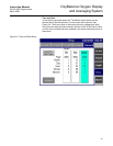
OxyBalance Oxygen Display
and Averaging System
http://www.processanalytic.com
Section 3 Setup
Overview . . . . . . . . . . . . . . . . . . . . . . . . . . . . . . . . . . . . . . . page 3-1
Setup . . . . . . . . . . . . . . . . . . . . . . . . . . . . . . . . . . . . . . . . . . page 3-1
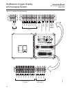
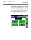
OVERVIEW This section provides information on setup and configuration of the
OxyBalance Oxygen Display and Averaging System
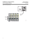
SETUP Each O
2
probe generates a 4-20 mA output signal that is received by the
OxyBalance system. When a probe channel detects a current signal greater
than 3.5 mA, that probe is considered active, and is automatically made
available. It is not necessary to tell the OxyBalance that a probe is present. It
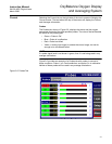
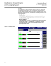
is automatically detected and used. Table 3-1 shows how the OxyBalance
system interprets and displays these signals.
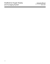
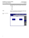
Table 3-1. Signal Interpretation
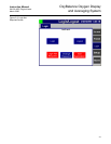
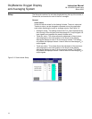
After these signals are converted into an O
2
% they are displayed on the
touch screen interface. The rest of this section will outline the necessary steps
to configure and operate the OxyBalance system through the touch screen
interface.
Before starting to install this equipment, read the "Safety Instructions" in Appendix A: Safety
Data. Failure to follow the safety instructions could result in serious injury or death.
Disconnect all power before installing or replacing components. Failure to disconnect power
may result in electrical shock and/or damage to the equipment.
4-20 mA Signal Value Status Display Color
<3.5 mA Probe Inactive Not Shown
3.5 mA to 3.6 mA
Probe Failed
Red
3.6 mA to 3.8 mA Reading Under Range Yellow
3.8 mA to 20.5 mA Good Reading Green
20.5 mA to 21 mA Reading Over Range Yellow
>21 mA Probe Failed Red