


Instruction Manual
IM-106-4050 Original Issue
March 2006
1-5
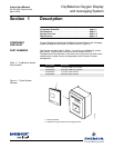
OxyBalance Oxygen Display
and Averaging System
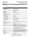
SPECIFICATIONS Specifications for the OxyBalance system are listied in Table 1-2.
Table 1-2. OxyBalance Specifications
(1)
Specifications are subject to change without notification. Our policy is one of continuous
improvement and we reserve the right to change specifications.
(2)
1.5A above 40
o
C.
SPECIFICATIONS
(1)
Ambient Environment
Temperature specification 23
o
F to 149
o
F (-5
o
C to 65
o
C)
Ambient temperature effect on electronics Less than .01% of reading per 10
o
C
Vibration IEC 68-2-6 and ISA S37.3
Shock IEC 68-2-31 and ISA S37.3
Enclosure NEMA 4X
Area Classification General Purpose
Power Requirements 100-240 VAC, 50/60 Hz
MicroLogix 1200
Resistive Load on Current Output 0 to 500 Ohms (includes wire resistance)
Input Impedance for Current Terminal 275 Ohms
PanelView Plus 600
Minimum On-State Current 2.0 mA at 10V dc
Nominal On-State Current 8.9 mA at 24V dc
Maximum On-State Current 12. mA at 30V dc
Current per Group Common 8A
240V ac (Maximum Volts) 2.5A
(2)
(Amperes Continuous)
120V ac (Maximum Volts) 2.5A
(2)
(Amperes Continuous)
125V dc (Maximum Volts) 1.0A (Amperes Continuous)
24V dc (Maximum Volts) 2.0A (Amperes Continuous)
I/O
Signal Inputs 4-20 mA (qty. 1 to 8 O
2
probes)
Signal Outputs 4-20 mA (qty, 1 to 8 pass through each probe, qty. 4 programmable averages)
Signal Output Resolution (for averages) 12 bit
Signal Output Resistive Load Less than 500 ohms
Discrete Inputs "IN CAL" (qty. 2 to 8 from individual probes)
Relay Outputs
"LOSS OF PLC"
"AVERAGE WARN" if one or more probes drop out of an average.
"AVERAGE FAILED" for each average when only one probe in the average
remains valid.
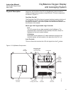
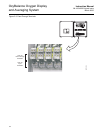
Architecture
Each probe utilizes its own autonomous conditioning electronics, including its
own power supply. Any failure in the OxyBalance system will not affect the
individual 4-20 mA signals going to the control room for each probe.
Logic 4 programmable averages from 2-8 probes
Individual probes removed from average if
1.) Probe fails (4-20 mA to default condition of 3.5 mA or 21 mA
2.) Probe is in cal (SPS / IMPS contact, must share with control room)
Signal Security
4-20 mA signals to be wired in series to the PLC and to the DCS I/O marshalling
panel such that the loss of the PLC will not affect the transmission of the
individual probe signals to the DCS. If PLC power, I/O cards or processor card(s)
are lost, 4-20 mA signals from the probes are still transmitted to the control room.
Personnel Security Password protection configuration changes in programmable averages.
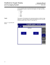
Color Graphic Display
Size 6" diagonal
Type Color Active Matrix, TFT LCD
Resolution 320 by 240 min. Touch screen operator interface