


6
Table of Contents (continued)
6. Diagrams
Introduction................................................................................................................................................37
General Schematic Notes............................................................................................................................37
Index...............................................................................................................................................53
Figures
2-1. Verification Test Setup.................................................................................................................................... 17
2-2. Verification Test Setup.....................................................................................................................................18
3-1. Bias Voltage to Switching Amplifier Assemblies.............................................................................................28
3-2. AC Programming Signal Path ..........................................................................................................................29
4-1. Agilent Series 665xA/667xA Power Supply, Block Diagram..........................................................................34
6-1. Mechanical Layouts..........................................................................................................................................38
6-2. Agilent 6814B, 6834B, 6843A Front Frame Assembly....................................................................................39
6-3. A9 208/230V AC Input Board Parts Location .................................................................................................40
6-4. A9 208/230V AC Input Assembly Schematic..................................................................................................41
6-5. A9 400V AC Input Board Parts Location.........................................................................................................42
6-6. A9 400V AC Input Assembly Schematic .........................................................................................................43
6-7. A10 Auxiliary Power Supply Board Parts Location.........................................................................................44
6-8. A10 Auxiliary Power Supply Assembly Schematic..........................................................................................45
6-9. A14 Bias Power Supply Board Parts Location.................................................................................................46
6-10. A14 Bias Power Supply Assembly Schematic.................................................................................................47
6-11. A5 Range/Output/Phase Relay Schematic.......................................................................................................48
6-12. A5 Range/Output/Phase Relay Driver Schematic............................................................................................49
6-13. A4 Mother Board Parts Location.....................................................................................................................50
6-14. A8 DSP Board Parts Location.........................................................................................................................51
6-15. A6 Servo Board Test Point Locations.............................................................................................................52
Tables
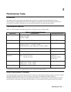
2-1. Test Equipment Required .....................................................................................................................................9
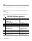
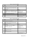
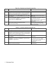
2-2. Performance Tests ..............................................................................................................................................10
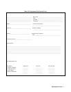
2-3. Performance Test Record Form...........................................................................................................................13
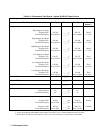
2-4. Performance Test Record Agilent 6814B............................................................................................................14
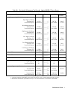
2-4. Performance Test Record Agilent 6834B............................................................................................................15
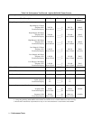
2-4. Performance Test Record Agilent 6843A............................................................................................................16
3-1. Test Equipment Requirements for Troubleshooting............................................................................................19
3-2. Specific Troubleshooting Procedures..................................................................................................................21
3-3. AC Power Source Troubleshooting Procedure....................................................................................................23
3-4. A9 208/208 Input Power Supply Troubleshooting..............................................................................................25
3-5. A9 Option 400 (400V) AC Input Power Supply Troubleshooting ......................................................................25
3-6. A10 Auxiliary Power Supply Troubleshooting....................................................................................................26
3-7. Al4 Option 400 Bias Power Supply Troubleshooting .........................................................................................26
3-8. A4 Mother Board Troubleshooting .....................................................................................................................27
3-9. A5 Mother Board Troubleshooting .....................................................................................................................27
5-1. Agilent 68l4B, 6834B, 6843A Replacement.......................................................................................................35
6-1. General Schematic Notes.....................................................................................................................................37