


Troubleshooting
21
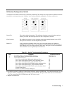
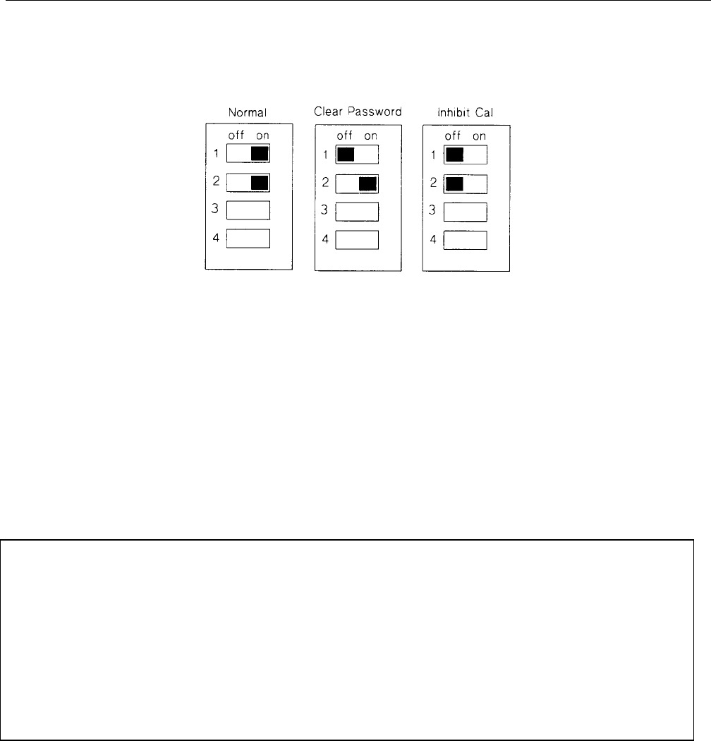
Calibration Configuration Switch
An internal set of switches control access to calibration commands. The switches are located on the A8 DSP board and are
accessible by removing the top cover. Switches 1 and 2 set the calibration configuration. The three positions are:
Normal Cal This is the default switch position. The calibration functions are accessible after entering a
numeric password. The default password is 0 and is changeable by the user.
Clear Password The calibration password is reset to 0 and the remote programming language is set to SCPI.
This option is useful if the user has forgotten the password.
Inhibit Cal In this position the calibration of the power source cannot be changed. All calibration
commands are disabled. If the CAL ON command is sent with the switch in this position, an
Out Of Range error will be displayed on the front panel. This option is useful in installations
where calibration access is guarded by instrument seals.
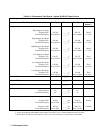
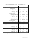
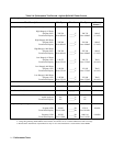
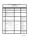
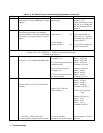
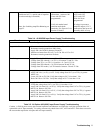
Table 3-2. Specific Troubleshooting Procedures
Step Symptom Corrective Action
1.
No output voltage / front panel display and fan off go to table 3-3
2.
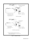
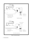
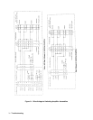
No or limited output / front panel display and fan on go to figure 3-2
3.
Turn-on Self Test Errors
Error l Non-volatile RAM RD0 section checksum failed Rl
Error 2 Non-volatile RAM CONFIG section checksum failed Rl
Error 3 Non-volatile RAM CAL section checksum failed Rl
Error 4 Non-volatile RAM WAVEFORM section checksum failed Rl
Error 5 Non-volatile RAM STATE section checksum failed Rl
Error 6 Non-volatile RAM LIST STATE section checksum failed Rl
Error l0 RAM selftest r2
Error 11 to 18 DAC self tests, l through 8 r2
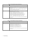
rl- Re-initialize unit and re-calibrate. If unit still has RAM error, replace A8 DSP board. To re-initialize unit turn CAL ON,
then press 0 and 9, simultaneously. Press scroll key to model number, then press Enter. When unit is re-initialized all
CAL data, user-defined WAVEFORM data, and LIST data is erased.
r2 -Replace A8 DSP board.