


Performance Tests
10
provided. Select an adequate gauge wire for load tests using the procedures given in the operating manual for connecting
the load.
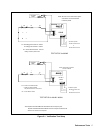
Current-Monitoring Resistor
To eliminate output current measurement error caused by voltage drops in the leads and connections, connect the
current-monitoring resistor as a four terminal device.
Performance Tests
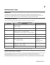
Performance tests check all the specifications of the ac source. The various tests are grouped under Table 2-2. If more than
one meter or a meter and an oscilloscope are used, connect each to the sense terminals by separate leads to avoid mutual
coupling effects.
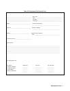
Performance Test Record Sheets
When performing the tests in this chapter, refer to the Performance Test Record sheets ( Table 2-3 and Table 2-4 ) at the
end of this chapter. Table 2-3 is for recording common information, such as test equipment used and environmental
conditions. Table 2-4 is for recording the actual measurements.
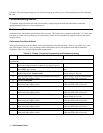
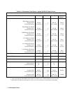
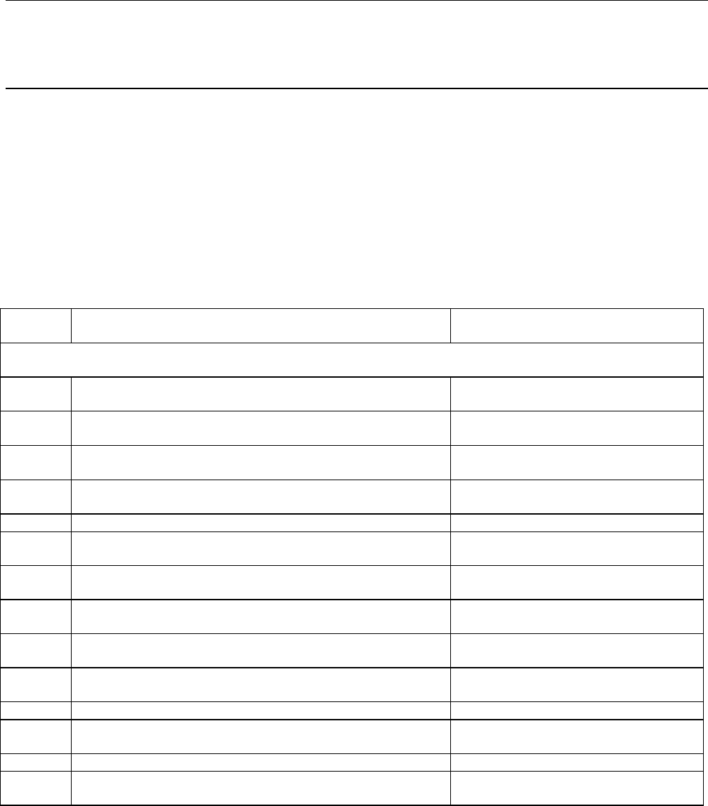
Table 2-2. Voltage / Frequency Programming and Readback Accuracy
Step Action Normal Result
This procedure verifies that the voltage programming and GPIB readback and front panel display functions are within
specifications.
1
Turn off ac source. Connect DVM and Ratio Transformer if
used across output terminals as shown in Test Setup Figure 2-1.
2
Turn on ac source with no load. Press [Shift] [Output], display
reads *RST, press [Enter].
*RST resets ac source to known factory
state.
3
Program VOLT:ALC EXT, VOLT 300, FREQ 45, CURR 10
Enable output press [Output on/off].
CV annunciator on.
Output voltage at 300 volts.
4
Record output voltage / frequency measurements from DVM /
front panel and frequency meter.
Output voltage / frequency measurements
within specified limits on test card.
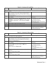
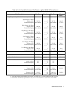
5
Program FREQ 400.
6
Record output voltage / frequency measurements from DVM /
front panel and frequency meter.
Output voltage / frequency measurements
within specified limits on test card.
7
Program FREQ 1000.
8
Record output voltage / frequency measurements from DVM /
front panel and frequency meter.
Output voltage / frequency measurements
within specified limits on test card.
9
Program VOLT:RANGE 150, VOLT 150, FREQ 45.
CV annunciator on.
Output voltage at 150 volts.
10
Record output voltage / frequency measurements from DVM /
front panel and frequency meter.
Output voltage / frequency measurements
within specified limits on test card.
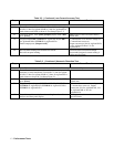
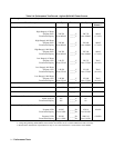
11
Program FREQ 400.
12
Record output voltage / frequency measurements from DVM /
front panel and frequency meter.
Output voltage / frequency measurements
within specified limits on test card.
13
Program FREQ 1000.
14
Record output voltage / frequency measurements from DVM /
front panel and frequency meter.
Output voltage / frequency measurements
within specified limits on test card.