


Troubleshooting
27
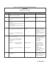
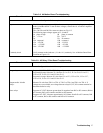
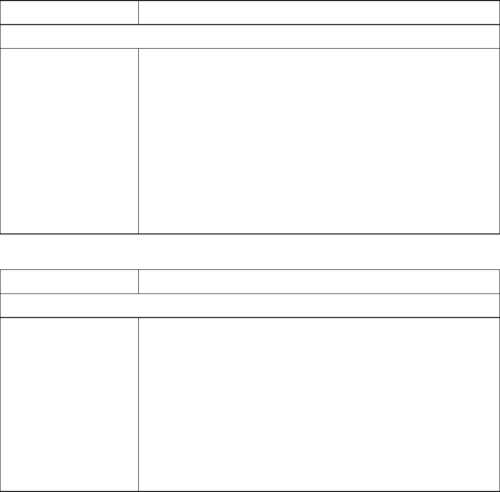
Table 3-8. A4 Mother Board Troubleshooting
Procedure Action
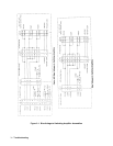
See figure 6-13 for test points.
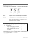
Inputs
Continuity check
The following voltage tests verify that the correct input operational voltages are available
to the A4 mother board. To test for these voltages, remove the Al, A2 and A3 amplifier
assemblies.
The +300 Vdc and 300 Vdc return are shown on Fig 6-13.
The following input voltages appear at J2, J4 and J6.
IA phase A high IB phase A common
2A +5V sec 2B *OVT
3A 3B D common
12A common 1 12B common 1
13A -15VSW 13B -15VSW
15A + 15VSW 15B +15VSW
16A + 15VSW1 16B + 15VSW1
Verify common mode inductors ( L1 thru L6 ) continuity. See A4 Mother Board Parts
Location on Figure 6-13.
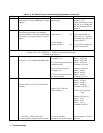
Table 3-9. A5 Relay / Filter Board Troubleshooting
Procedure Action
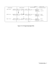
See figure 6-11 and 6-12 for test points.
Range relays Program VOLT 50, CURR:LEV 3, Output On.
Program high range: Measure 25 volts from J2-1 to J2-3, J2-2 to J2-4, J2-5 to J2-7,
J2-6 to J2-8, J2-9 to J2-11 and J2-10 to J2-12.
Program low range: Measure 50 volts from J2-1 to J2-3, J2-2 to J2-4, J2-5 to J2-7,
J2-6 to J2-8, J2-9 to J2-11 and J2-10 to J2-12.
Output enable / disable
Relays
Measure 50 volts from TB1-1 to TB1-6, TB1-3 to TB1-6 and TB1-4 to TB1-6. If
voltages are not available, test voltage between relays K5, K7, K8 common terminal to
determine defective relay.
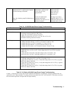
Sense relays Program ACL:INT: Measure greater than 10 megohms from R43 to K5 common, R44 to
K7 common, R45 to K8 common and R46 to K9 common.
Program ACL:EXT: Measure approximately 105 Kohms from R43 to K5 common, R44
to K7 common, R45 to K8 common and R46 to K9 common.