


Troubleshooting
24
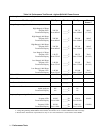
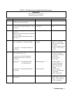
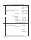
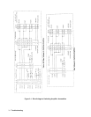
Table 3-3. AC Power Source Troubleshooting Procedures (continued)
Step Procedure Indication Action
7
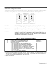
Relays energize, fans are on, but no front
panel display. Press the [ Shift ] key a couple
of times.
Shift annuniciator on front
panel toggles.
Check +5Vhpib and +/-15V
at A10J1, J2, J3.
Check communication from
A8 DSP to A11 front panel.
A8 DSP assembly may be
defective.
8
One or more outputs are missing.
The following procedures will attempt to
isolate the defective assembly by tracking the
bias voltages, ac program signal or ac output
signal.
300 Vdc on Cl. Yes
300 Vdc on C1. No
All bias voltage
present see fig 6-7. No
Check A4F1,F2,F3 Fuses
Verify A9 Input PS see
table 3-4 or 3-5. If option
400 model also verify A14
bias see table 3-7.
Verify all bias voltages are
present. See table 3-6.
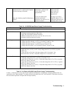
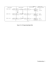
Front panel display on, fans on.
Program VOLT 100, CURR:LEV 3, Output On using front panel keypad
for following procedures:
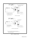
9
Tracking ac program signal.
See figure 3-2 AC Programming Signal Path.
Check A8 DSP assembly.
See figure 6-14
If 1.1 Vrms not present replace
A8DSP assembly
Check A6 Servo assembly.
See figure 6-15
If 1.6 Vrms not present replace
A6 Servo assembly.
Measure 1.1 Vrms for
Phase 1 A8U740-9
Phase 2 A8U770-9
Phase 3 A8U774-9
Common is J724-2,4.
Measure 1.6Vrms at
Phase 1 A6TP-3
Phase 2 A6TP-5
Phase 3 A6TP-7
Common at A6TP-1
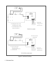
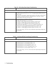
10
Tracking AC output signal.
Also see Table 3-9 to verify A5 Relay/Filter
assembly.
CAUTION – HIGH VOLTAGE
To verify amplifier output connect test leads,
Check A5 Relay assembly.
Relays A5K5,A5K7 and
A5K8 defective ?
.
A1,A2,A3 amplifier
assemblies are good if voltage
Check 100 Vrms at
Phase 1 A5TB1-1
Phase 2 A5TB1-3
Phase 3 A5TB1-4
Common at A5TB1-5
If 100 Vrms not present
Then
Measure 100 Vrms at
Phase 1 A5L1
Phase 2 A5L2
Phase 3 A5L3
Common at A5TP-8
Measure approx. 34 Vrms
between: