


Principles of Operation
31
4
Principles of Operation
Introduction
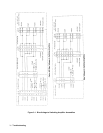
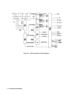
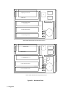
Figure 4-1 ( at end of this chapter ) is a block diagram showing the major circuits within the ac source. The ac source
consists of the following modules:
Al, A2, A3 Switching Amplifiers Modules
A4 Mother Board Assembly
A5 Range Relay and Filter Assembly
A6 Servo ( Control ) Assembly
A7 IEEE488 ( GPIB ) & RS232 Interface Assembly
A8 Digital Signal Processing ( DSP ) Assembly
A9 Input Power Assembly
A10 Auxiliary Power Supply Assembly
Al 1 Front panel Assembly
A12 Input Filter PC Assembly
A13 Bridge Capacitor Filter Assembly
A14 Bias Power Supply ( option 400 only )
General Description
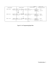
The 3 phase input power is connected to TBl on the rear panel, then routed through Fl, F2 and F3 to the RFI filter, FLI, to
relay Kl. The 3 phase input power is also connected to the A9 Input power assembly. When relay Kl closes the 3 phase
input is connected to power rectifier CRl, Ll and Cl to create 300 Vdc required by the power amplifiers Al, A2 and A3. The
amplifier assemblies in concert with the output filter and range relays produce the programmed waveform at the
programmed frequency and voltage. The 300 Vdc is also used by the A10 Auxiliary power supply board to produce the bias
voltages required by support circuits.
A1, A2, A3 Switching Amplifier Modules
The switching amplifier modules consist of a heat sink assembly, control board and power board. The 3 amplifier modules
are identical and can be interchanged for troubleshooting assistance. The amplifier assemblies can only be replaced as a
complete assembly, they are not repairable to the component level. The Agilent 6814B uses 2 amplifier assemblies
connected in parallel to provide 3000 watts single phase AC output power. The Agilent 6834B uses 3 amplifier assemblies
connected in a
3-phase configuration with each amplifier providing 1500 watts AC output power per phase. The 6843A uses three
amplifiers connected in parallel to provide 4800 watts single phase AC output power. When an amplifier assembly is
replaced it will be necessary to balance the amplifier, see paragraph on page 3-4 Switching Amplifier Output Balance
Adjustments. Amplifiers from [ 6814A, 6834A ] or [ 6843A ] or [ 6814B, 6834B ] Models are NOT INTERCHANGABLE.
See Chapter 5 Replaceable Parts listing for correct replacement assembly.
A4 Mother Board Assembly
The A4 mother board interconnects the Al, A2 and A3 amplifier assemblies with the A6 servo assembly, the 300 Vdc rail
voltage and the +/-15 Vdc bias supply. There are 10 amp fuses located in the +300 Vdc line to each amplifier assembly. The
Agilent 6814B and 6834B A4 assemblies are not interchangeable.