


Diagrams
37
6
Diagrams
Introduction
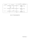
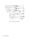
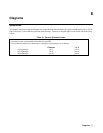
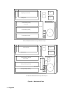
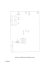
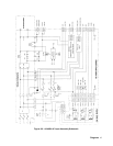
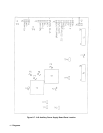
This chapter contains drawings and diagrams for troubleshooting and maintaining the Agilent 6814B and 6834B AC Power
Source/Analyzers. Unless otherwise specified in the drawings, a drawing or diagram applies to all models and input voltage
options.
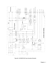
Table 6-1. General Schematic Notes:
1. All resistors are in ohms ± 1%, 1/8 W, unless otherwise specified.
2. All capacitors are in microfarads unless otherwise specified.
3. Unless otherwise noted, bias connections to integrated-circuit packages are as follows:
Common + 5 V
14-pin packages pin 7 pin 14
16-pin packages pin 8 pin 16
20-pin packages pin 10 pin 20