


Troubleshooting
23
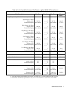
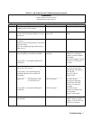
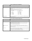
Table 3-3. AC Power Source Troubleshooting Procedures
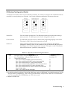
DANGER
Lethal voltages are present when
Instrument covers are removed.
Step Procedure Indication Action
1
Turn off ac mains, disconnect load, and
configure unit for local sensing.
2
Turn on unit and verify that ac power is on
by observing if front panel display is on and
fans are on.
No front panel, no fans, no
relay click ?
Check F1, F2, F3 on rear
panel.
3
Turn off power supply and remove top cover
as follows:
Remove 9 screws from top and 3 screws from
each side of unit.
Lift cover straight up being careful of lip on
front of cover.
4
Turn on supply and listen for clicking sound (
relays energizing ) on A9 Input assembly.
** See table 3-7 A14 Option 400 Bias PS
verification
No relay click, relays do not
energize?
See fig 6-3 & 6-4
Check A9 1/4 amp fuse.
Check 24 volt bias Option
400 models
See fig 6-6,6-9&6-10 Check
A14 Fl, F2, F3 Check 24
volt bias
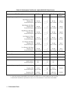
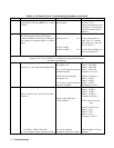
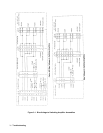
5
Relays energize but no front panel display
and no fans. 300 Vdc on Cl.
** See table 3-4 A9 200/208 Input PS
verification & table A10 Auxiliary PS
verification.
_______________________________
300 Vdc present ?
_____________________
No 300 Vdc then
See fig 6-4 Check CR1,
A9F2,F3,F4 A9K1,K2,K3
300 Vdc OK
See fig 6-7 & 6-8
Check A10F1
____________________
Option 400 500 Vdc across C9 &
C10 300 Vdc on C1.
** See table 3-5 A9 Option 400 Input PS
verification.
500 Vdc present ?
300 Vdc present ?
No 500 Vdc then
See fig 6-6 Check CR1,
A9F2,F3,F4 A9K1,K2
Check 24 V from A14
assembly
No 300 Vdc then
Check bias voltages from
A14 assembly
Replace A9 assembly
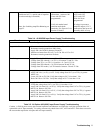
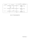
6
Relays energize, fans are on, but no front
panel display.
+5VDC @ A10J6 ? See fig 6-7 & 6-14
Check voltages at A10J6
Check +5V at A8J724-7 to
A8J724-2,4 common