


Troubleshooting
25
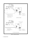
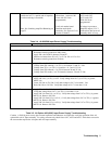
One to outside end of C1 and the other to
outside end of C3. ( outside end of capacitor
is end toward edge of heatsink )
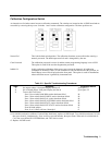
Note: See Switching Amplifier Balancing on
page 22.
is present at C1/C3
connections ( measure 100
Vrms with 300 Vrms
programmed )
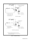
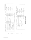
Verify A4 mother board
common mode choke
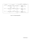
continuity. See figure 6-13 for
location of chokes.
A1C1 and A1C3
A2C1 and A2C3
A3C1 and A3C3
With 100 Vrms
programmed.
If voltage is present at
amplifier output ( C1/C3
connections) but not on A5
assembly check A5 assy.
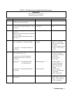
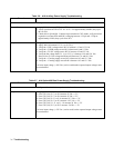
Table 3-4. A9 208/208 Input Power Supply Troubleshooting
Procedure Action
See figure 6-3 and 6-4 for test points and schematic.
Surge Limit Circuit 1. Measure resistance from Jl-l to Jl-7 or Jl-2 to Jl-8 or Jl-3 to Jl-6.
Resistance must be greater than 100 k ohms.
2. Apply 208 volts 50/60 Hz between E4 and E7.
3. Measure resistance from Jl-l to Jl-7 or Jl-2 to Jl-8 or Jl-3 to Jl-6.
Resistance must be greater than 20 ohms.
Bias Voltages 1. Apply 208 volts 50/60 Hz between E4 and E7.
2. Voltage from ZR1 cathode (+) to TP1 (-) is between 23 and 25.5 Vdc.
3. Voltage from TP3 (+) to TP1 (-) is between +11.5 and 12.5 Vdc.
4. Voltage from ZR2 cathode (+) to TP4 is between 20 and 22 Vdc.
5. Voltage from ZR3 anode (+) to TP4 must be between –20 and -22 Vdc.
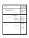
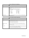
UVOV Detector 1. Apply 208 volts 50/60 Hz between E4 and E7.
2. Apply 300 Vdc (+) to El, (-) to E2. Verify voltage from U6-7(+) to TPI(-) is greater
than 9 Vdc.
3. Lower 300 Vdc to 220 Vdc. Verify that voltage at U6-7 is less than 1 Vdc.
4. Raise 300 Vdc to 395 Vdc. Verify that voltage at U6-7 is less than 1 Vdc.
Phase Loss Detector 1. Apply 208 volts 50/60 Hz between E4 and E7.
2. Verify that voltage from U4-7(+) to TP1(-) is less than 1 Vdc.
3. Apply 300 Vdc from Jl-l(+) to Jl-2(-). Verify that voltage from U4-7 to TP1(-) is greater
than 9 Vdc. Remove 300 Vdc.
4. Apply 300 Vdc from Jl-2(+) to Jl-3(-). Verify that voltage from U4-7 to TP1(-) is greater
than 9 Vdc. Remove 300 Vdc.
5. Apply 300 Vdc from Jl-3(+) to Jl-l(-). Verify that voltage from U4-7 to TP1(-) is greater
than 9 Vdc. Remove 300 Vdc.
Table 3-5. A9 Option 400 (400V) Input Power Supply Troubleshooting
Caution: A 500Vdc power source plus external capacitors and inductors are required to verify the operation of the A9
option 400 volt AC Input assembly. For safety concerns only check fuses A9F1, A9F2 and A9F3. If this does not resolve
the concern then replace the A9 option 400 AC Input assembly.