


Performance Tests
12
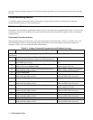
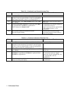
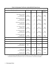
Table 2-2. ( Continued ) rms Current Accuracy Test
Step Action Normal Result
This test verifies the measurement accuracy of the rms current readback.
1
Turn off ac source. Connect Current Shunt, 7.5 ohm for Agilent
6814B, 15 ohm for Agilent 6834B or 5 ohm for Agilent6843A
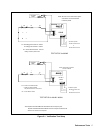
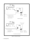
load resistors and DVM as shown in Test Setup Figure 2- 2.
2
Turn on ac source. Press [Shift] [Output] display reads *RST
press [Enter].
*RST resets ac source to known factory
default state.
3
Program VOLT 100, CURR 10 for Agilent 6814B, CURR 5
for Agilent6834B or CURR 15 for Agilent6843A.
Enable output press [Output on/off].
CC annunciator on or increase voltage till
CC annuniciator comes on.
Output current near 10A for Agilent6814B;
5A for Agilent 6834B or 15A for
Agilent6843A.
4
Record DMM reading and calculate rms current.
Record front panel reading.
Difference between measured output
current and front panel current reading is
within specified limits.
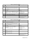
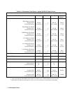
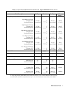
Table 2-2. ( Continued ) Harmonic Distortion Test
Step Action Normal Result
This test measures the total harmonic distortion of the output sinewave at full power.
1
Turn off ac source. Connect Audio Analyzer across output
terminals (or ratio transformer if used) and 7.5 ohm for Agilent
6814B, 15 ohm for Agilent 6834B or 5 ohms for Agilent6843A
load resistors as shown in Test Setup Figure 2-1 .
2
Turn on ac source. Press [Shift] [Output] display reads *RST
press [Enter].
*RST resets ac source to known factory
default state.
3
Program output voltage to VOLT:RANGE 150, VOLT 150,
CURR 20 for Agilent6814B, CURR 10 for Agilent 6834B or
CURR 32 for Agilent6843A.
CV annunciator on or reduce voltage until
CV annunciator comes on. Output
current near 20A for Agilent6814B, 10A
for Agilent6834B or 30A for
Agilent6843A
4
Record the total harmonic distortion reading from the audio
analyzer and front panel display.
Readings are less than maximum
specified limits.