


Principles of Operation
32
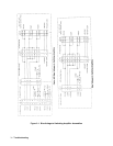
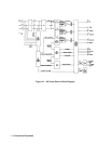
A5 Relay Range / Sense Assembly
The A5 assembly consists of the output voltage filters, the output voltage range relays A5Kl, A5K2 and A5K3, the output
voltage disconnect relays A5K5, A5K6, A5K8 A5K9 and remote sense relays A5K4, A5K7 and all associated circuits. It
also interconnects the A7 GPIB/RS232 assembly, A11 front panel assembly and A8 DSP assembly with each other and the
trigger and DFI/RI signals. The Agilent 6814B and 6834B A5 assemblies are not interchangeable.
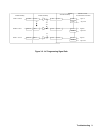
A6 Servo ( Control ) Assembly
The A6 servo or control assembly consists of the gate control circuits for the Al, A2 and A3 power amplifiers where
required. It also contains the voltage and current control amplifiers and receives the voltage and current programming
information from the A8 DSP assembly. It interconnects the range and protection signals between the A5 and A8
assemblies. This assembly is not component level repairable. The Agilent 6814B and 6834B A6 assemblies are not
interchangeable.
A7 IEEE488 (GPIB) / RS232 Interface Assembly
The A7 interface contains the CPU and logic circuits for communicating with either an GPIB or RS232 computer/controller.
This assembly is not component level repairable. This assembly is interchangeable with all AC power sources.
A8 Digital Signal Processing Assembly
The A8 DSP board contains the CPU, ROMs, Digital to Analog and Analog to Digital circuits to control the output voltage
and output current settings. The A8 board also contains all the logic circuits for generating arbitrary waveforms, frequency
changes and phase control. At power on the DSP board performs a self-test and will report a failure via the front panel
display. This assembly is not component level repairable and is not interchangeable between an Agilent 6814B and 6834B.
A9 Input Power Assembly - ( 208 volt input )
The A9 input power assembly provides a current limit circuit to initially charge Cl to 300 Vdc, a phase loss detection
circuit, the undervoltage / overvoltage detection circuits, and +/- l5VSW to the A10 auxiliary power supply assembly. When
S1, on/off switch, is closed a single phase is used to power two bias transformers generating the +/-15 Vdc, 12 Vdc for the
protection circuits and 24 Vdc to the current limit relays Kl, K2 and K3. There are 4 fuses on the A9 board. Fuse A9F1 is in
series with Sl on/off switch, if A9F1 is open the Agilent 6834B will not function in any form. The remaining 3 fuses, A9F2,
A9F3 and A9F4 are in series with the current limit resistors and relays. If all 3 fuses are open the unit will not function and
if 1 or 2 fuses are open the phase loss status bit be true and full output power will not be available. This assembly is not
component level repairable except for fuses. This assembly is interchangeable between an Agilent 6814B and 6834B.
A9 Input Power Assembly - ( 400 volt input )
The A9 input power assembly provides a current limit circuit to initially charge C9 and C10 to 550 Vdc, a step-down
switching regulator to power the +300V on C1, a phase loss detection circuit and the undervoltage / overvoltage detection
circuits. When S1, on/off switch, is closed a single phase is used to power three bias transformers on the A12 Bias board,
The A12 Bias board provides +16 Vdc, +15 Vdc, -5 Vdc, 12 Vdc for the protection circuits and 24 Vdc to the current limit
relays Kl and K2. There are 3 fuses on the A9 board. The 3 fuses, A9F2, A9F3 and A9F4 are in series with the current limit
resistors and relays. If all 3 fuses are open the unit will not function and if 1 or 2 fuses are open the phase loss status bit be
true and full output power will not be available. This assembly is not component level repairable except for fuses. This
assembly is interchangeable between a 6814B and 6834B.