


M100EU – OPERATIONS MANUAL TELEDYNE INSTRUMENTS
Addendum to M100E Manual - P/N 04145 TROUBLESHOOTING & REPAIR
Because the threads of the plastic screws are easily da
maged it is highly recommended to use new
screws when reassembling the unit.
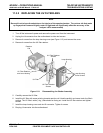
9. Carefully take out the assembly consisting of the HVPS, the gasket, preamp a
ssembly and the PMT.
10. Change the PMT or the HVPS or both, clean the PMT glass tube
with a clea
n, anti-static wipe and do
not touch it after cleaning.
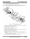
11. If the cold block or TEC is to be changed disconnect the TEC dr
iver board from the preamplifier board.
a) Remove the cooler fan duct (4 screws
on its sid
e) including the driver board.
b) Disconnect the driver board from the TEC and set the
sub-assembly aside.
c) Remove the end plate with the cooling fins (4 scre
ws) and sli
de out the PMT cold block assembly,
which contains the TEC.
d) Unscrew the TEC from the cooling fins and the cold
block and replace it with a new unit.
12. Re-assemble the TEC subassembly in reverse order.
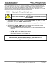
NOTE
The thermo-electric cooler needs to be mounted flat to the heat sink.
If there is any significant gap, the TEC might burn out.
Make sure to apply heat sink paste before mounting it and tighten the screws evenly and cross-wise.
a) Make sure to use thermal grease between the TEC and the cooling fins as well as between the TEC
and the cold block.
b) Align the side opening in the cold block with the hole in the PMT ho
using where the sample Chamber
attaches.
c) Evenly tighten the long mounting screws for good thermal conductivity.
13. Re-insert the TEC subassembly.
Make sure that the O-ring is placed properly and the assembly is tightened evenly.
14. Insert the LED and thermistor into the cold bloc.
15. Re-insert the PMT/HVPS subassembly.
Don’t forget the gasket between HVPS and PMT.
Use new plastic screws to mount the PMT assem
b
ly on the PMT cold block.
16. Insert the new desiccant bags.
17. Reconnect the cable from the preamp board to the b
a
ck of the Sync Demod board then carefully
reattach the Sync Demod board to the housing
Make sure that the gasket is between the back of the board and the front of the PMT hou
sing.
Be sure to tighten these screws evenly,
18. Reconnect the cables and the reaction cell
19. Replace the sensor assembly into the chassis and fa
sten with fou
r screws and washers.
20. Reconnect all electrical and pneumatic connections, leak check the system and power up the analyzer.
Verify the basic operation of the analyzer using the ET
EST and OT
EST features (see Section 6.9.5 &
6.9.6 of the M100E Manual - P/N 04145) or by measuring calibrated zero and span gases.
21. Perform a PMT Hardware calibration (see Section 11
.6.6 of the M100E Manual - P/N 04145)
22. Perform a zero point and span calibration (See Chapter 7 of the M100E Man
ual - P/N 04145)
05944 Rev B 35
DCN 5063 PRINTED DOCUMENTS ARE UNCONTROLLED