


TELEDYNE INSTRUMENTS M100EU – OPERATIONS MANUAL
TROUBLESHOOTING & REPAIR
Addendum to M100E Manual - P/N 04515
The UV outpu
t level of the lamp is not even across the entire length of the lamp. Some portions of the lamp
shine slightly more brightly than others. At the factory the position of the UV lamp is adjusted to optimize the
amount of UV light shining through the UV filter/lens and into the reaction cell. Changes to the physical
alignment of the lamp can affect the analyzer’s ability to accurately measure SO
2
. See Section 11.6.3.2 of the
M100E Manual (P/N 04145) for instructions on adjusting the lamp position.
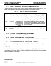
11.3.1.1 Adjusting the UV Lamp (Peaking the Lamp
CAUTION:
ALWAYS WEAR UV-PROTECTIVE, SAFETY GLASSES WHEN WORKING WITH THE UV
LAMP ASSEMBLY
1. Set the analyzer display to show the signal I/O function, UVLAMP_SIGNAL (see Section 11.1.3 of the
M100E Manual - P/N 04145). UVLAMP_SIGNAL is function 35.
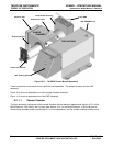
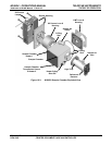
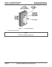
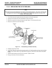
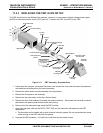
2. Slightly loosen the large brass thumbs
crew located on the shutter housing (see Figure 10-1) so that the
lamp can be moved.
3. While watching the UVLA
MP_SIGNAL reading, slowly rotate the lamp or move it back and forth
vertically until the UVLAMP_SIGNAL reading is at its maximum.
Best peak intensity will occur when the dot (or arrow) on top of the lamp is pointing in the direction of the
reaction cell.
Ideally, the reading should be 4000mV±200mV.
If UVLAMP_SIGNAL is lo
wer than 600mV, replace the lamp.
If UVLAMP_SIGNAL is greater than 4400 mV, adjust the pot on the UV reference board down until the
output reads 4400 mV, and then continue to peak the lamp.
NOTE:
DO NOT grasp the UV lamp by its cap when changing its position (see Figure 11-2).
Always grasp the main body of the lamp.
30 05944 Rev B
PRINTED DOCUMENTS ARE UNCONTROLLED DCN 5063