


TELEDYNE INSTRUMENTS M100EU – OPERATIONS MANUAL
TROUBLESHOOTING & REPAIR
Addendum to M100E Manual - P/N 04515
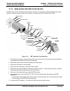
11.3.3 REPLACING THE PMT, HVPS OR TEC
The PMT should last for the lifetime of the analyzer. However, in some cases, the high voltage power supply
(HVPS) or the thermo-electric cooler (TEC) may fail. To replace the PMT, the HVPS or the TEC:
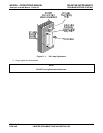
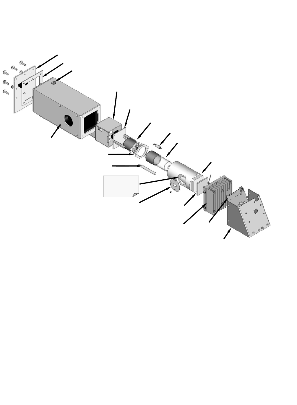
Sync/ Demod PCA
Leak Check Fitting
High
V
oltage Power Suppl
y
(HVPS)
PMT
PMT Cold Block
Connector to PMT
Pre Amp PCA
12V Power
Connector
Cooling Fan
Housing
TEC Driver
PCA
PMT Heat
Exchange Fins
Light from Reaction
Chamber shines
through hole in side
of Cold Block
Insulation Gasket
FOV Mask
Gasket
Thermo-Electric
Cooler (TEC)
PMT Temperature
Sensor
O-Test LED
Pre Amp
Shield
Pre Amp
PCA
PMT Housing
Figure 11-3: PMT Assembly - Exploded View
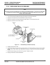
1. Power down the analyzer, disconnect the power cord, remove the cover and discon
nect all pneumatic
and electrical connections from the sensor assembly.
2. Remove the entire sensor module assembly from the analyzer.
3. Remove the fluorescence cell assembly.
4. Remove the two connectors on the Sync Demod board
5. Remove the Sync Demod Board (6 screws with plastic wa
sh
ers). Disconnect the electrical connector
that leads to the preamp board further inside the housing.
6. Remove all of the desiccant bags inside the PMT housing.
7. Along with the plate, slide out the OPTIC TEST LED
and the thermistor t
hat measures the PMT
temperature.
The thermistor will be coated with a white, thermal conducting paste. Do not contaminate the i
nside
of the housing or the PMT tube with this grease.
8. Unscrew the PMT assembly. It is held to the cold block by two plastic screws.
34 05944 Rev B
PRINTED DOCUMENTS ARE UNCONTROLLED DCN 5063