


M100EU – OPERATIONS MANUAL TELEDYNE INSTRUMENTS
Addendum to M100E Manual - P/N 04515 GETTING STARTED
05944 Rev
B 9
DCN 5063 PRINTED DOCUMENTS ARE UNCONTROLLED
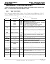
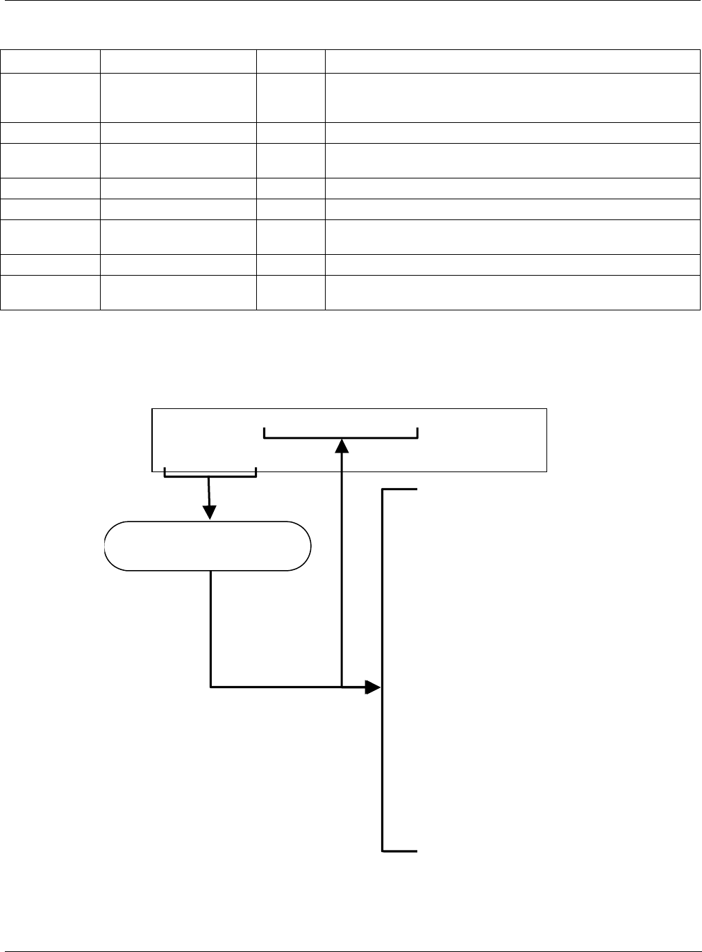
Table 3-1: Test Functions Defined
DISPLAY PARAMETER UNITS DESCRIPTION
OFFSET
SO
2
measurement Offset -
The overall offset of the instrument as calcu
lated during the last
calibration activity. The offset parameter is used to set the zero
point of the analyzer response.
HVPS
HVPS V The PMT high voltage power supply.
RCELL TEMP
SAMPLE CHAMBER
TEM
P
°C The current temperature of the sample chamber.
BOX TEMP
BOX TEMPERATURE °C The ambient temperature of the inside of the
analyzer case.
PMT TEMP
PMT TEMPERATURE °C The current temperature of the PMT.
IZS TEMP
1
IZS TEMPERATURE
1
°C
The current temperature of the internal zero/span option. Only
appears when IZS option is enabled
TEST
2
TEST SIGNAL
2
mV Signal of a user-defined test function on output channel A4.
TIME
CLOCK TIME
hh:mm:s
s
The current day time for iDAS records and calibration events.
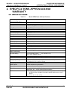
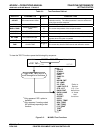
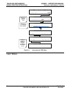
To view the TEST Functions press the following Key sequence:
RANGE
STABIL
STABIL2
PRES
SAMP FL
PMT
NORM PMT
UV LAMP
UV STAB
LAMP RATIO
STR. LGT
DARK PMT
DARK LAMP
SLOPE
OFFSET
HVPS
RCELL TEMP
BOX TEMP
PMT TEMP
IZS TEMP
1
TEST
2
TIME
SAMPLE
RANGE = 500.0 PPB
SO2 =XXX.X
< TST
TST >
CAL SETUP
1
Only appears if IZS option is
installed.
2
Only appears if analog output
A3 is actively reporting a test
function
Refer to
Section
6.2.1 for
definitions
of these
test
functions.
Toggle <TST TST> keys to
scroll throu
g
h list of functions
Figure 3-2: M100EU Test Functions