


TELEDYNE INSTRUMENTS M100EU – OPERATIONS MANUAL
GETTING STARTE
D
Addendum to M100E Manual - P/N 04515
8 05944 Rev B
PRINTED DOCUMENTS ARE UNCONTROLLED DCN 5063
3.3 FUNCTIONAL CHECK OF THE M100EU
To perform an initial functional check of the M100EU follow the steps contained in Section 3.2.4 of the M100E
Manual - P/N 04145, but use the Test functions described in below.
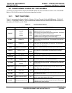
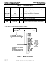
3.3.1 TEST FUNCTIONS
Table 3-1 supersedes the figure in Step 2 of Section 3.2.4 and Figure 6-2 of the M100E Manual - P/N 04145.
Table 11-1 supersedes Table 6-2. The only differences between the M100E an
d M100EU’s test functions are
the addition of STABIL2 and UV STAB.
Table 3-1: Test Functions Defined
DISPLAY PARAMETER UNITS DESCRIPTION
RANGE
RANGE
- -
RANGE1
RANGE2
PPB,
PPM,
UGM &
MGM
The Full Scale limit at which the repo
rting range of the analyzer’s
ANALOG OUTPUTS is currently set.
THIS IS NOT the Physical Range of the instrument. See Section
6.7 of M100E manual for more information.
If DUAL or AUTO Range modes have been selected, two
RANGE functio
n
s will appear, one for each range.
STABIL
STABILITY ppb
Standard deviation of SO
2
Concentration readings. Data points
are recorded every ten seconds. The calculation uses the last
25 data points.
STABIL2
STABILITY ppb
Standard deviation of SO
2
Concentration readings, per EPA.
Data points are recorded every 120 seconds. The calculation
uses the last 25 data points.
PRES
SAMPLE PRESSURE in-Hg-A
The current pressure of the sample
gas as it enters the sample
chamber, measured between the SO
2
and Auto-Zero valves.
SAMP FL
SAMPLE FLOW
cm³/min
(cc/m)
The flow rate of the sample gas through the sample chamber.
Th
is value is not measured but calculated from the sample
pressure.
PMT
PMT Signal mV The raw output voltage of the PMT.
NORM PMT
NORMALIZED PMT
Signal
mV
T
he output voltage of the PMT after normalization for offset and
temperature/pressure compensation (if activated).
UV LAMP
Source UV Lamp
Intensity
mV The output voltage of the UV reference detector.
UV STAB
Stability of UV Lamp
Intensity
mV
Standard deviation of UV reference detector output. Data points
are recorded
every ten seconds. The calculation uses the last
25 data points.
LAMP RATIO
UV Source lamp ratio %
The current output of the UV referenc
e detec
tor divided by the
reading stored in the CPU’s memory from the last time a UV
Lamp calibration was performed.
STR. LGT
Stray Light ppb
The offset due to stray light recorded by the CPU during the last
zero-point cal
ibration performed.
DRK PMT
Dark PMT mV
The PMT output reading recorded the la
st time the UV source
lamp shutter was closed.
DRK LMP
Dark UV Source Lamp mV
The UV reference detector output readin
g recorded the last time
the UV source lamp shutter was closed.
SLOPE
SO
2
measurement Slope -
The sensitivity of the instrument as calculate
d during the last
calibration activity.
The slope parameter is used to set the span
calibration point of the analyzer.
(table continued)