


TELEDYNE INSTRUMENTS M100EU – OPERATIONS MANUAL
THEORY OF OPERATION
Addendum to M100E Manual - P/N 04515
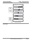
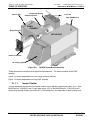
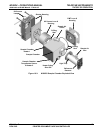
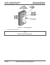
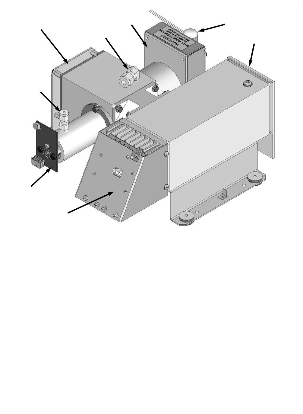
PMT HOUSING
Reaction Cell
Sample Gas Outlet
Sample Gas Inlet
PMT PREAMP PCA
Lamp Shutter Housing
UV LAMP
Reference Detector
SAMPLE
CHAMBER
PMT Cooling System
Figure 10-2: M100EU Sensor Module Assembly
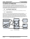
These compo
nents are divided into two significant subassemblies. The sample chamber and the PMT
assembly.
Figure 10-3 shows an exploded view of the sample chamber assembly
Figure 11-3 shows an exploded view of the PMT Assembly
10.1.1.1 Sample Chamber
The main electronic components of the sample chamber are the reference detector(see Section 10.2.2 of the
M100E Manual - P/N 04145); the UV Lamp (see Section 10.2.1 of the M100E Manual - P/N 04145) and its
electronically operated shutter (see Section 9.2.1 of this addendum); and the sample chamber heating circuit,
24 05944 Rev B
PRINTED DOCUMENTS ARE UNCONTROLLED DCN 5063