


Appendices
Test Bed Receiver Subsystem Addendum – Rev 1 27
FUNCTIONAL OVERVIEW
MILLENNIUM-GLONASS GPSCARD SYSTEM
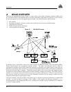
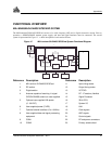
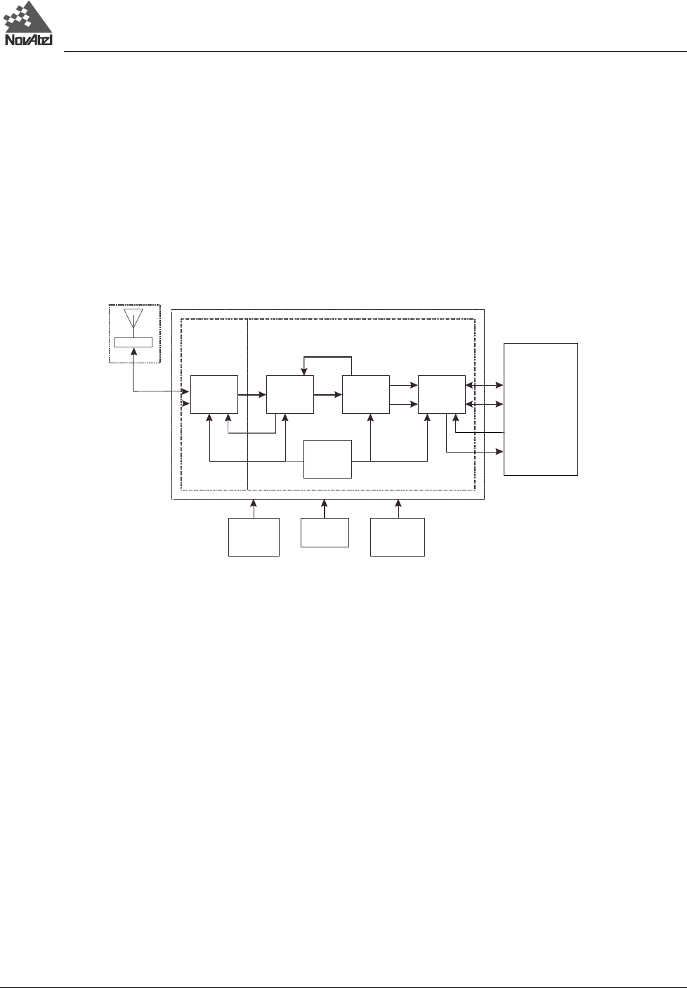
The MiLLennium-GLONASS GPSCard consists of a radio frequency (RF) and a digital electronics section. Prior to
operation, a GPS/GLONASS antenna, power supply, and data and signal interfaces must be connected. The overall
system is represented in Figure 15. A brief description of each section follows.
Figure 15 MiLLennium-GLONASS GPSCard System Functional Diagram
1
2
3
5
6
7
8
9
10
11
12
13
14 15
16 17
18
19
19
20
21
22
23
4
Reference Description Reference Description
1 MiLLennium-GLONASS GPSCard 11 Input timing strobe
2 RF section 12 Output timing strobe
3 Digital section 13 VCTCXO
4 Antenna capable of receiving L1 signal 14 RF - IF sections, NovAtel
GPS/GLONASS antenna or user-supplied 15 Signal Processor
5 Optional user-supplied LNA power 16 32-bit CPU
(0 - 30 VDC) 17 System I/O
6 User-supplied power (5 VDC) 18 LNA
7 Optional external oscillator (5 or 10 MHz) 19 Clock signals
8 User-supplied data and signal processing 20 AGC signals
equipment 21 Control signals
9 COM1 22 RF and power connectors
10 COM2 23 Primary antenna feed