


2 - Installation
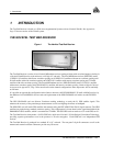
Test Bed Receiver Subsystem Addendum – Rev 1 15
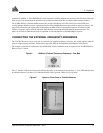
CONNECTING THE EXTERNAL POWER INPUT
The Test Bed Receiver requires one source of external regulated power. The input can be in the +22 to +30 V DC range.
The receiver draws up to 3 A at start-up, but the steady-state requirement is approximately 1.5 A.
Five and twelve volt power supplies are installed internally within the enclosure. The 5-volt supply is used to power the
two receivers and the antenna. The 12-volt supply is used for OCXO power. Both of these supplies receive their power
from a connector on the enclosure back panel and accept DC power within a voltage range of +22 to +30 volts.
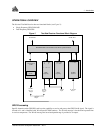
The power-input connector on the Test Bed Receiver is a 3-position chassis jack. It mates to a 3-position inline plug
supplied with the Test Bed Receiver. Pin 1 (+22 to +30 V DC), and Pin 2 (GND) connect to the Test Bed Receiver’s
internal power supply, which performs filtering and voltage regulation functions. Pin 3 serves as ground connection
protection. Refer to Figure 9.
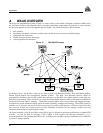
Figure 9 External Power Connections - Test Bed
Pin 1
Pin 2
Pin 3
Notch
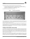
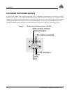
USING THE 10 MHz OUTPUT SIGNAL
The 10 MHz output provides a high-stability reference clock to the Test Bed Receiver. It permits the synchronization of
the two receiver subsystems in the Test Bed Receiver. See Internal and External Oscillators on Page 12 for more
information.
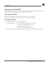
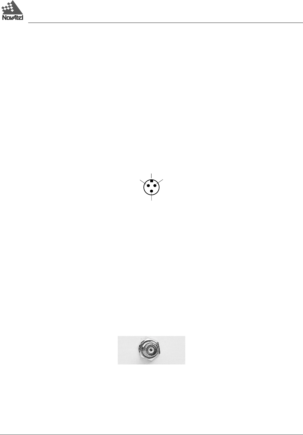
If the receiver is to be operated from the internal 10 MHz OCXO then a jumper cable is connected from the 10 MHz
output BNC connector to the 10 MHz input BNC connector (see Figure 10). If the receiver is to be operated from an
external 10 MHz frequency source such as a Cesium or Rubidium oscillator then that frequency reference will be
connected to the 10 MHz IN port on the rear panel of the receiver. In that case the 10 MHz OUT port should be
terminated with a 50
Ω terminator.
Figure 10 10 MHz Output – Test Bed